. 2024 Apr;23(4):560-569.
doi: 10.1038/s41563-024-01810-6. Epub 2024 Feb 9.

Artificial-goosebump-driven microactuation

Affiliations

Artificial-goosebump-driven microactuation

Mingchao Zhang et al. Nat Mater. 2024 Apr.

Abstract

Microactuators provide controllable driving forces for precise positioning, manipulation and operation at the microscale. Development of microactuators using active materials is often hampered by their fabrication complexity and limited motion at small scales. Here we report light-fuelled artificial goosebumps to actuate passive microstructures, inspired by the natural reaction of hair bristling (piloerection) on biological skin. We use light-responsive liquid crystal elastomers as the responsive artificial skin to move three-dimensionally printed passive polymer microstructures. When exposed to a programmable femtosecond laser, the liquid crystal elastomer skin generates localized artificial goosebumps, resulting in precise actuation of the surrounding microstructures. Such microactuation can tilt micro-mirrors for the controlled manipulation of light reflection and disassemble capillary-force-induced self-assembled microstructures globally and locally. We demonstrate the potential application of the proposed microactuation system for information storage. This methodology provides precise, localized and controllable manipulation of microstructures, opening new possibilities for the development of programmable micromachines.


Conflict of interest statement

The authors declare no competing interests.

Figures

Fig. 1
Fig. 1. Artificial-goosebump-driven microactuation system.
a, Schematic illustration showing the phenomenon of fine hairs standing on the skin upon stimulation and the underlying mechanism of goosebumps. b, Schematic illustration of the piloerection-inspired microactuation system, where the goosebumps, generated by the local laser heating, induce a temporary local curvature that deflects the 2PP-printed passive microhairs. c, Schematic illustration showing the fabrication process of artificial polymeric (IP-S photoresist) microhair arrays using 2PP on a tri-network LCE skin. d, Scanning electron microscopy (SEM) image displaying a 2PP-printed microhair (with a width of 8 µm and height of 150 µm) on the LCE skin. e, SEM image showing a 2PP-printed microhair array on the LCE skin. f,g, Schematic illustrations presenting the mechanism involved in artificial goosebump generation for the microactuation, where a broadening of an artificial goosebump causes unintended actuation of microstructures (f), while a localized goosebump brings about precise and targeted actuation (g). RM257, 1,4-bis-(4-(3-acryloyloxypropyloxy)benzoyloxy)-2-methylbenzene; 5CB, 4-cyano-4′-pentylbiphenyl.
Fig. 2
Fig. 2. Thermal actuation of the tri-network LCE film.
a, Schematic illustration depicting the fabrication process of the tri-network LCE. PETMP, pentaerythritol tetrakis(3-mercaptopropionate); EDDET, 2,2-(ethylenedioxy)diethanethiol. b, Cross-polarized optical images displaying the evolution of a typical LCE (with 25 wt% dopant, small mobile liquid crystal molecules, 5CB) at different temperatures. c, Cross-polarized optical images showing the LCE samples with varying amounts of 5CB at 80 °C. D with subscripts (∥ and ⊥) denotes the lengths of the LCE measured along (∥) and perpendicular to (⊥) the director. d, Anisotropic shape changes of the LCE samples with and without 25 wt% 5CB dopant. e, Anisotropic deformations of the LCE samples with different amounts of 5CB dopant. f, Differential scanning calorimetry measurements conducted on the LCE samples with different dopants. For LCE without doping, two peaks include the glass transition temperature (Tg) and nematic-to-isotropic transition temperature (TN–I) of the crosslinked bi-network of LCE. For LCE samples with doping, the three peaks observed can be attributed to the Tg and TN–I of the dopant inside the LCE, and the TN–I of the crosslinked bi-network LCE. Source data
Fig. 3
Fig. 3. Generation of local artificial goosebumps on the LCE skin via a fs laser.
a, FE simulation illustrating the generation of an artificial microscale goosebump using a laser with a scanning area of 1 × 1 µm2. b, Topographic contour displaying the FE-simulated microscale goosebump. c, Optical images showcasing the goosebump generated on the LCE surface, where arrays of 2PP-printed micropillars (diameter, 1 µm; height, 2 µm; array spacing, 10 µm) are used to track the displacement of the LCE surface (using a laser with a scanning area of 5 × 5 µm2). d, Experimental tracking of surface displacement on a LCE surface without 5CB dopant actuated by a laser with a scanning area of 5 × 5 µm2. e, Experimental tracking of surface displacement on an LCE surface with a 50% 5CB dopant. f, Displacement evolution of a tracking micropillar (located 50 µm along the director direction from the laser centre) on the LCE with varying amounts of 5CB. g, FE simulation demonstrating the displacement of the LCE surface without 5CB dopant, actuated by a laser with a scanning area of 5 × 5 µm2. h, FE simulation showing the displacement of the LCE surface with 50% 5CB dopant, actuated by the same laser. i,j, Schematics (left) and FE simulations in temperature distribution (right) of the LCE without (i) and with (j) 5CB dopant, actuated by the same laser. It indicates that the decrease in thermal conduction of the LCE, resulting from the doping of small mobile molecules, contributes to the localization of laser heating and induces large and site-specific local deformations (artificial goosebumps). Tmax is the simulated maximum temperature generated in the spot. λ is the thermal conductivity with the superscripts (0 and 1) representing the LCE without (0) and with (1) 5CB dopant, respectively. The subscripts (∥ and ⊥) denote measurements taken along (∥) and perpendicular to (⊥) the director. Source data
Fig. 4
Fig. 4. Light-powered goosebump-driven passive microhairs with 2-DOF motion.
a, Optical images depicting the deflection of microhairs driven by goosebumps powered by a fs laser at a scanning area of 5 × 5 µm2. b, Schematic illustration demonstrating the actuation of microhairs through goosebump-induced deformations. c, Displacement of the microhair tip when actuated by a laser at different spacings (S) between the laser centre and the microhair. Data points are shown as mean ± s.d. (n = 15). d, Displacement of the microhair tip with varying heights (H) when actuated by the same laser. Data points are shown as mean ± s.d. (n = 15). e, Frequency response of the hair motion driven by different laser scanning speeds. Data points are shown as mean ± s.d. (n = 15). f, Displacement extent of the microhair tip actuated by a laser with different scanning power levels. Data points are shown as mean ± s.d. (n = 15). g, Schematic illustration showcasing the free trajectories of the laser, enabling 2-DOF motions of the microhair tip. h, Snapshots of optical images illustrating a moving laser along a row of microhairs, sequentially inducing their motion. i, Trajectories (0–360° rotation) of the microhairs actuated by circular sweepings of the laser surrounding the microhairs with different spacings, with one example shown in the inset. Source data
Fig. 5
Fig. 5. Applications of the artificial-goosebump-driven microactuation systems.
a, Schematics illustrating micro-mirrors with for controllable light steering. b,c, SEM (b) and reflective optical (c) images of a 3D-printed micro-mirror with dimensions l1 = l2 = h = 100 µm. d, FE simulation illustrating the plane tilt of the micro-mirror driven by the generated artificial goosebump on the LCE skin. e, Schematic illustrating the process of capillary-induced self-assembly of printed high-aspect-ratio (slender) microstructures. r is the diameter of the slenders, d is the spacing distance of surrounding slenders and θ is the contacting angle of liquid and slenders. When the elastic restoring force (Fe) cannot resist the adhesion (Fa) of the slenders, the assembly is thus formed. f, Optical images of an example self-assembly during the liquid solvent evaporation process (development process). Scale bars are 30 µm. g, SEM image displaying the self-assembled microstructure. h, Schematic illustration demonstrating the disassembling mechanism of the assembled structure using the laser-driven goosebumps, which generate a disturbance force (Fg), such as shear (Fshear) or strain (Fstrain), that overcomes the cohesion (Fa) of the self-assembled structures, resulting in their disassembly. i, Application of the disassembling mechanism by employing a mushroom-like mirror as the basic assembling unit. When the micro-mirrors are assembled, light is scattered, leading to a dark view (black dashed box as in j), while disassembled mirrors reflect light, resulting in a bright view (red dashed box as in j). j, Optical images showing the 3D-printed mushroom-like mirror arrays. k, Optical images capturing the disassembling process of the assembled structures using a laser. Scale bars are 20 µm. l,m, SEM image (l) and reflective optical image (m) showing the assembled microstructures. n, Reflective optical image displaying the disassembled structure after the laser treatment. The red circles indicate the bottom positions of the mushroom-like mirror before (m) and after (n) the laser treatment.
Fig. 6
Fig. 6. Local disassembly of uniformly self-assembled mirror-pixels for information storage.
a, Strategy for generating uniform bi-mirror self-assemblies by adjusting the additional spacing (Δd) between mirror pairs. b, Quantitative analysis of the yields of bi-assemblies, tetra-assemblies and other assemblies as a function of Δd after being self-assembled. Data points are shown as mean ± s.d. (n = 12). c, Optical images depicting the self-assembled mirror arrays resulting from different values of Δd. The blue and red dashed boxes denote tetra-assemblies and bi-assemblies, respectively. The colour bar at the bottom explains the transition of different assemblies as the increase of Δd. d, Optical image showcasing large-area uniform bi-assemblies after being assembled. e, SEM image of uniform bi-assemblies. f, Schematic illustration showing the local disassembly of the uniform bi-assemblies, with 0 and 1 as in g. g, Optical image showing the local disassembly of the uniform bi-assemblies, where 0 stands for the assembled stage and 1 stands for the opened stage. h, Optical image showing written digital numbers from 0 to 9. i, Optical image showing written letters ‘MPI’. j, Optical image showing a written QR code with the content ‘Hello MPI-IS’. Defective pixels including unintended disassembly (0.16%) and unopened pixels (0.64%) are marked in red and blue rectangles, respectively. Source data
Extended Data Fig. 1
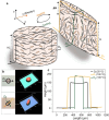
Extended Data Fig. 1. Spatial deformation (in x, y, and z direction) of the LCE.
a, Schematic illustration showing the spatial deformation of the LCE. b, Optical images and constructed 3D images of the LCE before and after heating. c, Height profiles of the LCE along and transverse to the director at 25 oC and 100 oC. Source data
Extended Data Fig. 2
Extended Data Fig. 2. Quantitative analysis of interfacial bonding strength and long-term actuation of microstructures.
a, Schematic of a printed architecture for detachment test. The architecture (IP-S) is composed of two vertical arrays of micropillars separated by a plane. The bottom micropillars (5×5 array; height: 50 µm; spacing: 400 µm) was printed to the LCE substrate, and the top dense and long micropillars (10×10 array; height: 200 µm; spacing: 150 µm) are designed to capture UV-curable glue (P/N6801, Norland Inc.) on the probe (connected to the load cell) through capillary infiltration. The plane is designed to prevent the contact of UV-curable glue with the bottom micropillars (as a separation barrier). b, Schematics of the detachment test process: (I) UV-curable glue was applied to the probe (connected to the load cell), and the probe slowly approached the sample at a speed of 5 μm/s and stopped as soon as the UV glue wetted and infiltrated into the top dense micropillars; (II) a 365 nm UV lamp (UV-15 S/L, Herolab) was employed to cure the glue for a duration of 20 min; (III) the probe began to ascend at a rate of 100 nm/s; (IV) the stretching leaded to sequential detachment of these micropillars, and finally they were completely detached from the LCE substrate. c, Profile of stress vs. stretching displacement during detachment. The insets are real-time captured optical images showing the micropillars are sequentially detached from the LCE substrate. d, Actuation displacement change of a micropillar subjected to the actuation of 30,000 cycles under a high frequency of 6 Hz. The inset is the schematic showing the actuation of a micropillar with a high frequency of actuation. Source data
Extended Data Fig. 3
Extended Data Fig. 3. Experimental and simulation results of artificial-goosebump-driven micro-mirrors for controllable light steering.
a, Experimental results demonstrating the tilting angle (α) of the mirror plane as a function of scanning power and the size of the laser spot. Data points are shown as mean ± s.d. (n = 6). b, Simulated plane positions of the micro-mirrors with different scale-down ratios driven by the same artificial goosebump, where the lateral size of the plane is set to be 100 µm for the micro-mirror with a scale-down ratio of 1. c, Simulated titling angles as a function of the scale-down ratios of the micro-mirrors. The inset is the SEM image of the printed micro-mirrors with different scale-down ratios. d, Simulation depicting the tilting direction of a micro-mirror subjected to two simultaneously applied laser spots.The bottom schematic shows any tilting direction of a micro-mirror can be achieved by cooperatively actuating the four supporting legs. Source data
Extended Data Fig. 4
Extended Data Fig. 4. Controllable manipulation of mushroom-like microstructures as a switch by laser.
a, SEM image illustrating an array of mushroom-like round mirrors. Round-shaped mirrors were employed to enable symmetric geometries for equal possibilities of interaction to their surroundings. b, SEM image showing two attached mushroom mirrors. c, Optical images capturing the manipulation process of controllably attaching and detaching two mushroom mirrors. By exposing the laser to the centre of two separated micromirrors along the director of the LCE (I and II), the shrinkage of the LCE along the director brings the mirrors closer, resulting in their attachment. Even after retracting the laser, the attached pair remains intact due to the cohesion between them (III). When the laser is applied to the surroundings of the attached mirrors, the resulting shrinkage at the laser induces a pulling force that separates and detaches adjacent mirror pairs (IV). This controllable on/off switching between attachment and detachment of the microstructures shows a promising micromachine application.

References

    1. Zhang S, et al. 3D-printed micrometer-scale wireless magnetic cilia with metachronal programmability. Sci. Adv. 2023;9:eadf9462. doi: 10.1126/sciadv.adf9462. - DOI - PMC - PubMed
    1. Ren Z, et al. Soft-robotic ciliated epidermis for reconfigurable coordinated fluid manipulation. Sci. Adv. 2022;8:eabq2345. doi: 10.1126/sciadv.abq2345. - DOI - PMC - PubMed
    1. Wang W, et al. Cilia metasurfaces for electronically programmable microfluidic manipulation. Nature. 2022;605:681–686. doi: 10.1038/s41586-022-04645-w. - DOI - PubMed
    1. Hu X, et al. Magnetic soft micromachines made of linked microactuator networks. Sci. Adv. 2021;7:eabe8436. doi: 10.1126/sciadv.abe8436. - DOI - PMC - PubMed
    1. Liu Q, et al. Micrometer-sized electrically programmable shape-memory actuators for low-power microrobotics. Sci. Robot. 2021;6:eabe6663. doi: 10.1126/scirobotics.abe6663. - DOI - PubMed