. 2024 Jan 30;24(3):896.
doi: 10.3390/s24030896.

The Feasibility and Accuracy of Holographic Navigation with Laser Crosshair Simulator Registration on a Mixed-Reality Display

Affiliations

The Feasibility and Accuracy of Holographic Navigation with Laser Crosshair Simulator Registration on a Mixed-Reality Display

Ziyu Qi et al. Sensors (Basel). .

Abstract

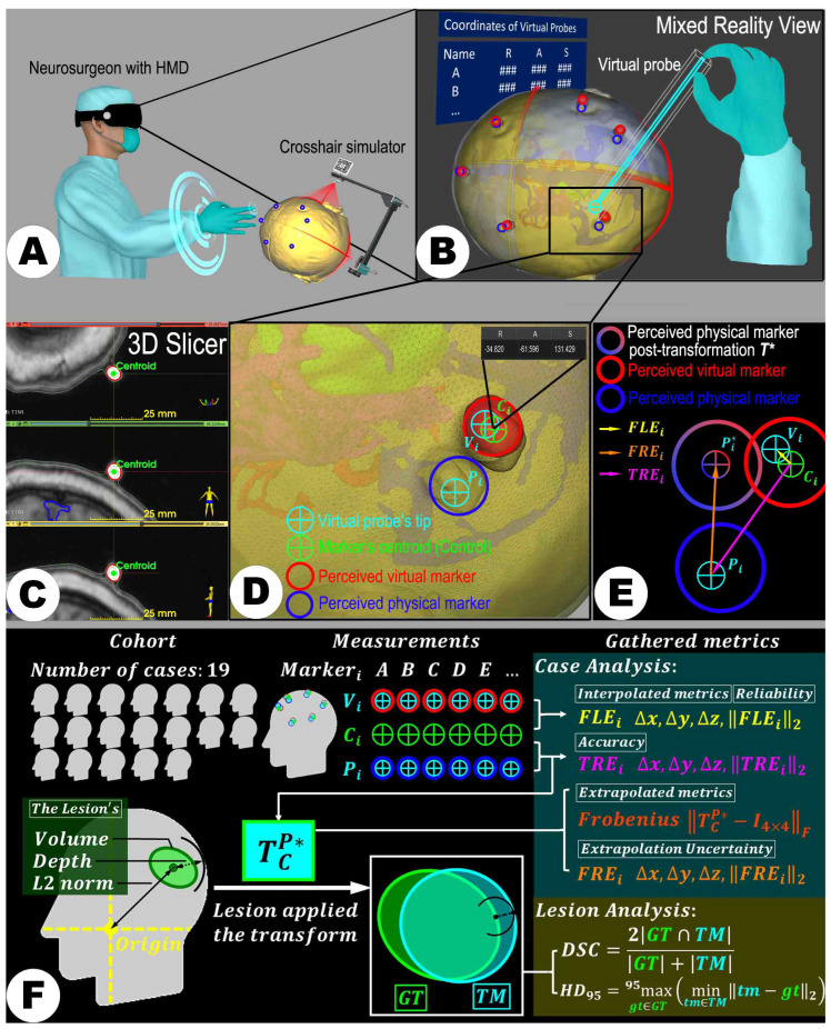
Addressing conventional neurosurgical navigation systems' high costs and complexity, this study explores the feasibility and accuracy of a simplified, cost-effective mixed reality navigation (MRN) system based on a laser crosshair simulator (LCS). A new automatic registration method was developed, featuring coplanar laser emitters and a recognizable target pattern. The workflow was integrated into Microsoft's HoloLens-2 for practical application. The study assessed the system's precision by utilizing life-sized 3D-printed head phantoms based on computed tomography (CT) or magnetic resonance imaging (MRI) data from 19 patients (female/male: 7/12, average age: 54.4 ± 18.5 years) with intracranial lesions. Six to seven CT/MRI-visible scalp markers were used as reference points per case. The LCS-MRN's accuracy was evaluated through landmark-based and lesion-based analyses, using metrics such as target registration error (TRE) and Dice similarity coefficient (DSC). The system demonstrated immersive capabilities for observing intracranial structures across all cases. Analysis of 124 landmarks showed a TRE of 3.0 ± 0.5 mm, consistent across various surgical positions. The DSC of 0.83 ± 0.12 correlated significantly with lesion volume (Spearman rho = 0.813, p < 0.001). Therefore, the LCS-MRN system is a viable tool for neurosurgical planning, highlighting its low user dependency, cost-efficiency, and accuracy, with prospects for future clinical application enhancements.

Keywords: augmented reality; automatic registration; dice similarity coefficient; head phantom; intracranial lesion; laser crosshair simulator; mixed reality; neuronavigation; neurosurgical planning; target registration error.


Conflict of interest statement

The authors declare no conflicts of interest. The funders had no role in the design of the study; in the collection, analyses, or interpretation of data; in the writing of the manuscript; or in the decision to publish the results.

Figures

Figure 1
Figure 1
An illustration of general paradigms in conventional navigation systems. (A) Fiducial-based registration employs identifiable external markers placed on the patient’s skin. These are reference points to align preoperative images with the patient’s physical space during surgery. (B) Surface-based registration utilizes the contours of the patient’s exposed surfaces to create a spatial map that aligns preoperative images with the patient’s anatomy in the operating room. (C) Automatic registration effectively aligns the captured three-dimensional (3D) volumetric data (reference image) with its origin of capture, utilizing scanner tracking mechanisms such as those in intraoperative scanners to guarantee precise alignment for navigation purposes.
Figure 2
Figure 2
Schematic of the study framework. LCS = laser crosshair simulator; MRN = mixed reality navigation.
Figure 3
Figure 3
Functionality of the laser crosshair simulator (LCS). The LCS replicates a scanner’s laser crosshairs, projecting dual laser lines onto a patient’s head as seen in CT or MRI environments (A,B). Its primary function is to facilitate the translation of scanning parameters across various spatial and temporal settings to establish the position for the reference image coordinate system (C). The black curved arrow links the tracking and virtual environments via the MR interface. Detection and recognition of the target images by the HMD prompt the initialization of the virtual space, anchoring its origin at the predetermined position. ((A) provided by Alamy, has undergone minor modifications by the authors to suit the specific context of this work. Alamy has granted copyright authorization for the use and adaptation of the image). RICS = reference image coordinate system.
Figure 4
Figure 4
The figure illustrates the technical validation process of the LCS-MRN system using the data of a 73-year-old female patient with a right parietal metastasis close to eloquent motor structures. (A) displays T1-weighted MRI data with key anatomical structures (green—lesion, bright red—markers, cyan—scalp quadrants, deep orange—arteries, dark blue—venous sinuses, light blue—ventricles, and magenta—pyramidal tract), markers, and laser positioning lines highlighted for 3D reconstruction. (B) shows the 3D-printed head phantom with integrated markers (blue arrows) and laser positioning lines (red arrows). (C) depicts the phantom affixed to a head clamp, indicating fixation points (red circles). (D) illustrates the deployment of the LCS and alignment of the laser crosshairs. (E) presents the interaction with holograms through the MR platform. (F,G) display the virtual probe positioning on virtual and physical markers, respectively. The visualization of the registration process and the subsequent data analysis, including the calculation of target registration error (TRE) and other metrics, is visually represented in (H,I). Detailed descriptions of each step, particularly the methodologies for measuring points and data processing, are discussed in the main text.
Figure 5
Figure 5
Compatibility processing of holograms for varying surgical positions. Panels (AD) display the head phantom in supine, prone, left-lateral, and right-lateral positions, respectively, highlighting the LCS-MRN system setup. Panels (EH) illustrate the different orientations of the RICS (brown) in comparison to the intermediate VCS (IVCS) (light green), the virtual coordinate system (VCS) (dark green), and the analysis coordinate system (ACS) (light blue) within the 3D Slicer software (Version 5.1.0) for each position, as well as their transformations (indicated by gradient color arrows): the Forward Engineering Matrix (FEM), Reverse Engineering Matrix (REM), and Handedness Conversion Matrix (HCM). Panels (IL), representing the FEM and REM, are customized for each surgical position to ensure accurate registration and analysis of the holograms within the LCS-MRN system. This process guarantees the precise display and visualization of MR content across different surgical scenarios.
Figure 6
Figure 6
An illustrative scheme demonstrates the quality assessment procedure. After registration of a set of holograms and the physical space (A) using the LCS, achieving theMRN registration, the tip of the virtual probe is positioned at the perceived centers of the virtual markers (red circles) and the physical markers (blue circles), respectively, and their 3D coordinates (automatically transformed into the reference image coordinate system (RICS)) were immediately reported and displayed (where ### represents the numerical values of R, A, or S) on the MR platform (B). Next, the coordinates reported underwent REM transformation. They were subtracted from the coordinates of the marker’s centroid, which were annotated in advance in 3D Slicer (C,D), resulting in two displacement vectors, i.e., fiducial localization error FLE and target registration error TRE (E). Moreover, the optimal rigid transformation TCP was calculated, ensuring the calculation of a set of extrapolative metrics, such as the fiducial registration error FRE and Frobenius norm FN. When TCP is applied to the original segmentation of the lesion (as the ground truth, GT), the transformed model (TM) is obtained, thereby allowing the calculation of the Sørensen–Dice similarity coefficient (DSC) and the 95% Hausdorff distance (HD95), focusing on the LCS-MRN accuracy regarding the lesion volume and shape (F).
Figure 7
Figure 7
3D-printed phantoms (rows 1, 3, 5) and corresponding holograms (rows 2, 4, 6) were generated from imaging data in all included 19 cases.
Figure 8
Figure 8
Visual outcomes and corresponding metrics for all 19 cases utilizing the LCS-MRN system. Each case features a metrics list displayed on the left column; holograms derived from segmentation results are exhibited in the central column, with two-dimensional (2D) contour representations on the top and 3D models displayed within an MR setting on the bottom. On the right column of a case display, extrapolated correspondence errors of the registered holograms are illustrated using pseudocolor scale maps. For comparative ease, identical planes from 2D images and consistent perspectives within the 3D space are utilized. Within this figure, the legend positioned at the lower right corner elucidates the scale map legend, hologram labeling, and the significance of the metrics list. In the legend, the symbol “##” denotes a numerical value. A single asterisk “*” signifies one lesion, and a double asterisk “**” two in a case. It is important to note that for cases with two lesions (Case_08 and Case_14), the metrics reported outside the brackets pertain to the larger lesion, while values within the brackets correspond to the smaller lesion.
Figure 9
Figure 9
Dual-sided deployment of LCS. Panels (A,B) exhibit the LCS’s MR interface with Vuforia image targets attached on both sides, captured in a simulated operative context with the LCS positioned on different sides of the phantom head. The images clearly demonstrate successful registration and visualization of the holograms, indicating reliable recognition and tracking by the LCS-MRN system. Panels (C,D) offer schematic diagrams, emphasizing the LCS’s placement versatility around the user, accommodating both left-sided and right-sided arrangements.
Figure 10
Figure 10
Landmark-based accuracy results. The bar chart displays the magnitude of displacement vectors (FLE, TRE, and FRE) for each case (A). Histograms show the distribution of the magnitudes of each displacement vector across all measurements with a fitted normal curve (BD). 3D scatter plots are based on the components of each displacement vector along the three primary axes of the reference image coordinate system, with color gradients representing vector magnitude. (EG). Clustered bar charts illustrate comparisons of displacement metrics (FLE, TRE, FRE, and FN) grouped by surgical position (H). The whiskers in (A,H) on the plot extend to the smallest and largest data points that fall within a distance of 1.5 times the interquartile range (IQR) from the lower (Q1) and upper (Q3) quartiles, respectively.

References

    1. Bopp M.H., Corr F., Saß B., Pojskic M., Kemmling A., Nimsky C. Augmented Reality to Compensate for Navigation Inaccuracies. Sensors. 2022;22:9591. doi: 10.3390/s22249591. - DOI - PMC - PubMed
    1. Carl B., Bopp M., Saß B., Pojskic M., Gjorgjevski M., Voellger B., Nimsky C. Reliable navigation registration in cranial and spine surgery based on intraoperative computed tomography. Neurosurg. Focus. 2019;47:E11. doi: 10.3171/2019.8.FOCUS19621. - DOI - PubMed
    1. Kiya N., Dureza C., Fukushima T., Maroon J. Computer navigational microscope for minimally invasive neurosurgery. Min-Minim. Invasive Neurosurg. 1997;40:110–115. doi: 10.1055/s-2008-1053429. - DOI - PubMed
    1. Kantelhardt S.R., Gutenberg A., Neulen A., Keric N., Renovanz M., Giese A. Video-assisted navigation for adjustment of image-guidance accuracy to slight brain shift. Oper. Neurosurg. 2015;11:504–511. doi: 10.1227/NEU.0000000000000921. - DOI - PubMed
    1. Stieglitz L.H., Fichtner J., Andres R., Schucht P., Krähenbühl A.K., Raabe A., Beck J. The silent loss of neuronavigation accuracy: A systematic retrospective analysis of factors influencing the mismatch of frameless stereotactic systems in cranial neurosurgery. Neurosurgery. 2013;72:796–807. doi: 10.1227/NEU.0b013e318287072d. - DOI - PubMed

LinkOut - more resources