

A self-stiffening compliant intracortical microprobe
- PMID: 38345721
- PMCID: PMC10861748
- DOI: 10.1007/s10544-024-00700-7
A self-stiffening compliant intracortical microprobe
Abstract
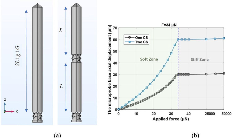
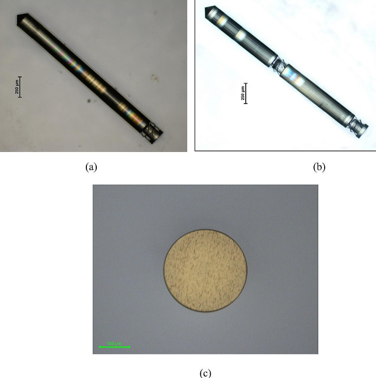
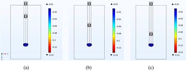
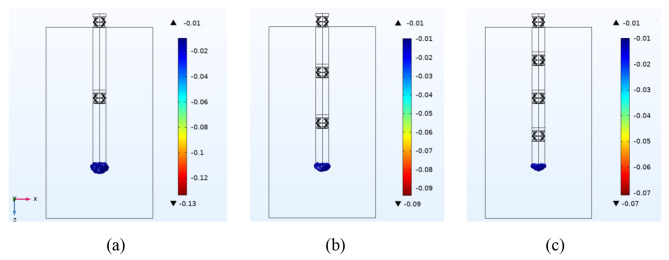
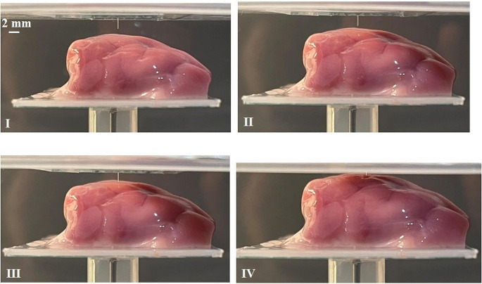
Utilising a flexible intracortical microprobe to record/stimulate neurons minimises the incompatibility between the implanted microprobe and the brain, reducing tissue damage due to the brain micromotion. Applying bio-dissolvable coating materials temporarily makes a flexible microprobe stiff to tolerate the penetration force during insertion. However, the inability to adjust the dissolving time after the microprobe contact with the cerebrospinal fluid may lead to inaccuracy in the microprobe positioning. Furthermore, since the dissolving process is irreversible, any subsequent positioning error cannot be corrected by re-stiffening the microprobe. The purpose of this study is to propose an intracortical microprobe that incorporates two compressible structures to make the microprobe both adaptive to the brain during operation and stiff during insertion. Applying a compressive force by an inserter compresses the two compressible structures completely, resulting in increasing the equivalent elastic modulus. Thus, instant switching between stiff and soft modes can be accomplished as many times as necessary to ensure high-accuracy positioning while causing minimal tissue damage. The equivalent elastic modulus of the microprobe during operation is ≈ 23 kPa, which is ≈ 42% less than the existing counterpart, resulting in ≈ 46% less maximum strain generated on the surrounding tissue under brain longitudinal motion. The self-stiffening microprobe and surrounding neural tissue are simulated during insertion and operation to confirm the efficiency of the design. Two-photon polymerisation technology is utilised to 3D print the proposed microprobe, which is experimentally validated and inserted into a lamb's brain without buckling.
Keywords: 3D printing; Buckling; Finite element method; Insertion; Intracortical microprobe; Self-stiffening.
© 2024. The Author(s).
Conflict of interest statement
The authors declare no conflicts of interests.
Figures


Similar articles
-
Ultra-miniature ultra-compliant neural probes with dissolvable delivery needles: design, fabrication and characterization.Biomed Microdevices. 2016 Dec;18(6):97. doi: 10.1007/s10544-016-0125-4. Biomed Microdevices. 2016. PMID: 27778225
-
Mechanical analysis and fabrication of a penetrating silicon microprobe as an artificial optic nerve visual prosthesis.Int J Artif Organs. 2012 Jan;35(1):34-44. doi: 10.5301/ijao.5000034. Int J Artif Organs. 2012. PMID: 22328332
-
Compliant intracortical implants reduce strains and strain rates in brain tissue in vivo.J Neural Eng. 2015 Jun;12(3):036002. doi: 10.1088/1741-2560/12/3/036002. Epub 2015 Apr 2. J Neural Eng. 2015. PMID: 25834105 Free PMC article.
-
Neural tissue-microelectrode interaction: Brain micromotion, electrical impedance, and flexible microelectrode insertion.J Neurosci Methods. 2022 Jan 1;365:109388. doi: 10.1016/j.jneumeth.2021.109388. Epub 2021 Oct 20. J Neurosci Methods. 2022. PMID: 34678387 Review.
-
A comparison of insertion methods for surgical placement of penetrating neural interfaces.J Neural Eng. 2021 Apr 26;18(4):10.1088/1741-2552/abf6f2. doi: 10.1088/1741-2552/abf6f2. J Neural Eng. 2021. PMID: 33845469 Free PMC article. Review.
Cited by
-
Mechanically-adaptive, resveratrol-eluting neural probes for improved intracortical recording performance and stability.Npj Flex Electron. 2025;9(1):64. doi: 10.1038/s41528-025-00440-5. Epub 2025 Jul 9. Npj Flex Electron. 2025. PMID: 40656548 Free PMC article.
References
-
- M.A. Arafat, L.N. Rubin, J.G.R. Jefferys, P.P. Irazoqui, 2019, ‘A Method of Flexible Micro-Wire Electrode Insertion in Rodent for Chronic Neural Recording and a Device for Electrode Insertion’, IEEE Transactions on Neural Systems and Rehabilitation Engineering, Neural Systems and Rehabilitation Engineering, IEEE Transactions on, IEEE Trans. Neural Syst. Rehabil. Eng, vol. 27, no. 9, pp. 1724-31 - PubMed
-
- D. Atkinson, T. D’Souza, J.S. Rajput, N. Tasnim, J. Muthuswamy, H. Marvi, Pancrazio, JJ 2021, ‘Advances in Implantable Microelectrode Array Insertion and Positioning’. Neuromodulation: J. Int. Neuromodulation Soc. - PubMed
-
- R. Biran, D.C. Martin, P.A. Tresco, 2005, ‘Neuronal cell loss accompanies the brain tissue response to chronically implanted silicon microelectrode arrays’, Experimental Neurology, vol. 195, no. 1, pp. 115 – 26 - PubMed
MeSH terms
LinkOut - more resources
Full Text Sources
