. 2024 Feb 14;13(1):48.
doi: 10.1038/s41377-024-01383-8.

Wearable and interactive multicolored photochromic fiber display

Affiliations

Wearable and interactive multicolored photochromic fiber display

Pan Li et al. Light Sci Appl. .

Abstract

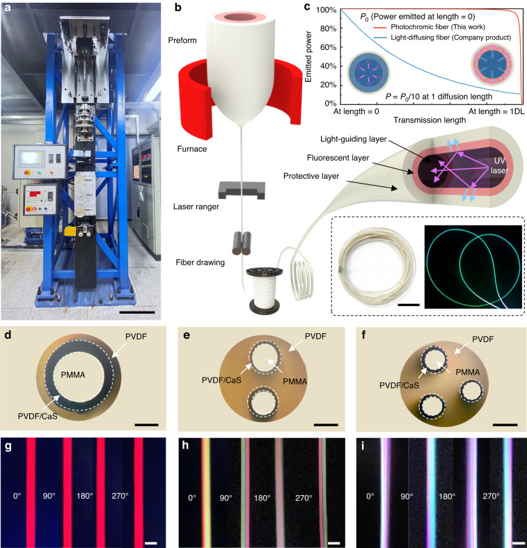
Endowing flexible and adaptable fiber devices with light-emitting capabilities has the potential to revolutionize the current design philosophy of intelligent, wearable interactive devices. However, significant challenges remain in developing fiber devices when it comes to achieving uniform and customizable light effects while utilizing lightweight hardware. Here, we introduce a mass-produced, wearable, and interactive photochromic fiber that provides uniform multicolored light control. We designed independent waveguides inside the fiber to maintain total internal reflection of light as it traverses the fiber. The impact of excessive light leakage on the overall illuminance can be reduced by utilizing the saturable absorption effect of fluorescent materials to ensure light emission uniformity along the transmission direction. In addition, we coupled various fluorescent composite materials inside the fiber to achieve artificially controllable spectral radiation of multiple color systems in a single fiber. We prepared fibers on mass-produced kilometer-long using the thermal drawing method. The fibers can be directly integrated into daily wearable devices or clothing in various patterns and combined with other signal input components to control and display patterns as needed. This work provides a new perspective and inspiration to the existing field of fiber display interaction, paving the way for future human-machine integration.


Conflict of interest statement

The authors declare no competing interests.

Figures

Fig. 1
Fig. 1. Fabrication and structural characterization of the photochromic fiber.
a Photograph of the industrial-scale fabrication line of the photochromic fiber. The scale bar corresponds to 0.5 m. b Schematic illustration of the fabrication of the photochromic fiber. The inset shows a photograph of the fabricated and illuminated photochromic fiber. The scale bar corresponds to 10 cm. c Comparison of the luminescence attenuation in the transmission direction between this work and the commercial product (light-diffusing fiber)[39]. df Cross-sectional optical micrograph of three types of photochromic fiber, showing a different number of cores in the fiber, d for single-core red color, e for dual-core red and green colors, and f for tri-core red, green, and blue colors. The scale bar in each case corresponds to 200 μm. gi Photographs of the photochromic fiber under radial observation, g for red color at 0°, 90°, 180°, and 270° angles, h for dual-core red and green colors at 0°, 90°, 180°, and 270° angles, and i for tri-core red, green, and blue colors at 0°, 90°, 180°, and 270° angles. The scale bar in each case corresponds to 500 μm
Fig. 2
Fig. 2. Luminescence performance of single-core photochromic fiber.
a Ray model diagram of the single-core photochromic fiber, including straight or bending cases. The diagrams show the phenomenon of refraction and total internal reflection of light rays in the longitudinal section of the fiber. b Luminous saturation threshold of the single-core photochromic fiber. c Dependence of fluorescence intensity and pump intensity on core radius at the output port of a 3 mm length fiber. d Variation of fluorescence intensity with different pumping power in the direction of fiber length. e Luminance at different rotating angles mapped into polar coordinates, measured from 0° to 360° in 30° increments. f Dependence of luminance ratio on bending radius, the bending radius was varied from 15 mm to 10 mm. g Dependence of luminance ratio (L/L0) on bending cycle (radius of curvature R = 15 mm). L0 and L correspond to luminance before and after bending or torsion, respectively
Fig. 3
Fig. 3. Luminescence performance of multicolored photochromic fiber.
a Schematic illustration of multicore photochromic fiber as viewed from the human eye. Adjusting the fiber shape and size parameters allows the circumferential color difference and fiber multi-color mixing effect to be optimized, and the discernible visual distance can be minimized. b The circumferential spectra of multicolored photochromic fiber, measured from 0° to 360° at 30° increments. c Dependence of x, y chromaticity coordinate on viewing angle. d Schematic diagram of the light field distribution radiation of three-color fluorescence in the fiber cross-section. e Dependence of color standard deviation on core spacing. f Dependence of color standard deviation on cladding radius. g Luminescence spectrum with the brightness ratios of blue to green shown on the right. The power of the blue-core coupling light source is unchanged, while the power of the green-core coupling light source is adjusted. h Luminescence spectrum with the brightness ratios of green to blue shown on the right. The power of the green-core coupling light source is unchanged, while the power of the blue-core coupling light source is adjusted. i x, y chromaticity coordinates are controlled by adjusting the light power of different cores. The chromaticity triangle is composed of the power ratios of the light sources coupled to the red, green, and blue cores, with the coordinates of the vertices from top to bottom being (0.217, 0.507), (0.496, 0.304), and (0.186, 0.128), respectively. The fiber can achieve all chromaticity values within the triangle by mixing light sources with different power ratios
Fig. 4
Fig. 4. Application scenarios of the photochromic fiber systems.
a Schematic illustration for the interaction system based on photochromic fiber. b Photograph of the wearable wristband. The scale bar corresponds to 2 cm. c Correspondence between capacitance response and light-emitting colors under different touch positions. d Photograph of the photochromic fiber integrated into T-shirts. The scale bar corresponds to a 10 cm. e Wearable interactive display system that reflects the user’s current emotional state based on his facial expression. f Photograph of the photochromic fiber in automotive interiors. The scale bar corresponds to 10 cm. g Photochromic fiber arranged in a fish tank to demonstrate its underwater illumination. The scale bar corresponds to 5 cm

References

    1. Qu CM, et al. Multifunctional displays and sensing platforms for the future: a review on flexible alternating current electroluminescence devices. ACS Appl. Electron. Mater. 2021;3:5188–5210. doi: 10.1021/acsaelm.1c00833. - DOI
    1. Zuo Y, et al. Flexible color-tunable electroluminescent devices by designing dielectric-distinguishing double-stacked emissive layers. Adv. Funct. Mater. 2020;30:2005200. doi: 10.1002/adfm.202005200. - DOI
    1. Lee Y, et al. Standalone real-time health monitoring patch based on a stretchable organic optoelectronic system. Sci. Adv. 2021;7:eabg9180. doi: 10.1126/sciadv.abg9180. - DOI - PMC - PubMed
    1. Tan YJ, et al. A transparent, self-healing and high-κ dielectric for low-field-emission stretchable optoelectronics. Nat. Mater. 2020;19:182–188. doi: 10.1038/s41563-019-0548-4. - DOI - PubMed
    1. Shi X, et al. Large-area display textiles integrated with functional systems. Nature. 2021;591:240–245. doi: 10.1038/s41586-021-03295-8. - DOI - PubMed