. 2024 Feb 20;15(1):1560.
doi: 10.1038/s41467-024-45783-1.

True amplification of spin waves in magnonic nano-waveguides

Affiliations

True amplification of spin waves in magnonic nano-waveguides

H Merbouche et al. Nat Commun. .

Abstract

Magnonic nano-devices exploit magnons - quanta of spin waves - to transmit and process information within a single integrated platform that has the potential to outperform traditional semiconductor-based electronics. The main missing cornerstone of this information nanotechnology is an efficient scheme for the amplification of propagating spin waves. The recent discovery of spin-orbit torque provided an elegant mechanism for propagation losses compensation. While partial compensation of the spin-wave losses has been achieved, true amplification - the exponential increase in the spin-wave intensity during propagation - has so far remained elusive. Here we evidence the operating conditions to achieve unambiguous amplification using clocked nanoseconds-long spin-orbit torque pulses in magnonic nano-waveguides, where the effective magnetization has been engineered to be close to zero to suppress the detrimental magnon scattering. We achieve an exponential increase in the intensity of propagating spin waves up to 500% at a propagation distance of several micrometers.


Conflict of interest statement

The authors declare no competing interests.

Figures

Fig. 1
Fig. 1. Implementation of spin-wave amplification.
a Schematics of the experiment. Spin-wave pulses are excited by a Au antenna and propagate in a 500-nm wide waveguide fabricated from a BiYIG(20 nm)/Pt(6 nm) bilayer. In-plane dc current flowing in the Pt layer is converted into an out-of-plane pure spin current Is (inset), which is injected into the BiYIG film and exerts anti-damping torque on the magnetization. b Optical micrograph of the sample. c Normalized BLS maps of the spin-wave intensity in the space-time coordinates recorded at I = 0 and 1.4 mA, as labeled. Dashed lines show the spatio-temporal shift of the edge of the spin-wave pulse corresponding to the group velocity of 135 m s−1. d Spatial dependence of the intensity of the spin-wave pulse measured at different dc currents, as labeled. Symbols show the experimental data. Solid straight lines show the exponential fit. The data are obtained at f = 5.025 GHz and H0 = 1.8 kOe applied at θ = 30°.
Fig. 2
Fig. 2. Effect of the angle of the static magnetic field on amplification and auto-oscillations.
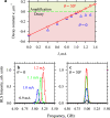
a Current dependence of the decay constant of spin-wave intensity obtained at θ = 0 and 30°, as labeled. Symbols show experimental data. Solid line is the linear fit of the data at θ = 30°. b, c BLS spectra of magnetization auto-oscillations recorded at the labeled values of the dc current at θ = 0 and 30°, respectively, without applying microwave pulses to the antenna. The data for θ = 0 and 30° are obtained at H0 = 2.0 and 1.8 kOe, respectively, to compensate for the frequency shift of the spin-wave dispersion spectrum.
Fig. 3
Fig. 3. Effects of PMA on the ellipticity of magnetization precession.
a In magnetic films, the magnetization precession is strongly elliptical due to the dynamic dipolar demagnetizing field hd. b In films with PMA, the dipolar field hd can be compensated by the effective field of the anisotropy ha resulting in a decrease in the ellipticity.
Fig. 4
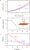
Fig. 4. Results of micromagnetic simulations of spin-wave dynamics in the nano-waveguide.
a Dispersion curves of spin waves calculated at β = 0.1° and θ = 0 and 30°, as labeled. b Angular dependence of the nonlinear frequency shift of the spin-wave spectrum calculated as the difference in the frequency of spin waves for the magnetization precession cone angles β of 10° and 0.1°. c Angular dependences of the ellipticity of the magnetization precession in the center and at the edge of the nano-waveguide. Curves are guides for the eye. These simulations points toward θ = 30° as a field angle, at which both the nonlinear frequency shift and the ellipticity almost vanish.
Fig. 5
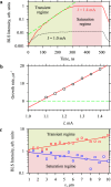
Fig. 5. Time constraints of the amplification process.
a Temporal dependences of the intensity of auto-oscillations after the start of the dc pulse recorded at I = 1.4 mA (solid curve). The dependence shows the transient regime and the saturation regime with a cross over at about 300 ns. Dashed curve shows the exponential increase of the intensity of auto-oscillations. Temporal dependence of the intensity of magnetic fluctuations (dotted curve) recorded at I = 1.0 mA is shown for reference. b Current dependence of the exponential growth rate of current-induced auto-oscillations. Symbols show the experimental data. Line is a linear fit. c Spatial dependences of the intensity of the signal spin-wave for the cases when the spin-wave pulse is applied during the time interval corresponding to the transient and saturation regime, as labeled. Symbols show the experimental data. Solid lines show the exponential fit. The data are obtained at f = 5.025 GHz and H0 = 1.8 kOe applied at θ = 30°.
Fig. 6
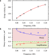
Fig. 6. Effects of the velocity of spin waves on the amplification efficiency.
a Frequency dependence of the group velocity. Symbols show the experimental data. Curve is the guide for the eye. b Frequency dependences of the decay constant obtained at I = 0 (point-down triangles) and at the maximum current (point-up triangles). Note that negative decay constants correspond to the spatial amplification of the wave. Curves show the results of calculations using Eq. (1). The data are obtained at H0 = 1.8 kOe applied at θ = 30°. The largest amplification efficiency is obtained for the slowest spin-waves.
Fig. 7
Fig. 7. Evidence of the coherence of the amplification process.
The dependences show the amplitude of the interference of the BLS signal carrying information about the spin wave with the reference light modulated by the signal used for the excitation of the spin wave with the phase shifted by Δφ = 0 – 360°. The data are obtained at x = 1 μm and x = 10 μm, as labeled, at I = 1.4 mA and f = 5.025 GHz. Symbols show the experimental data. Curves show the fit by a sinusoidal function.

References

    1. Neusser S, Grundler D. Magnonics: Spin waves on the nanoscale. Adv. Mater. 2009;21:2927–2932. doi: 10.1002/adma.200900809. - DOI
    1. Lenk B, Ulrichs H, Garbs F, Münzenberg M. The building blocks of magnonics. Phys. Rep. 2011;507:107–136. doi: 10.1016/j.physrep.2011.06.003. - DOI
    1. Chumak A, Vasyuchka V, Serga A, Hillebrands B. Magnon spintronics. Nat. Phys. 2015;11:453–461. doi: 10.1038/nphys3347. - DOI
    1. Yu H, et al. Approaching soft X-ray wavelengths in nanomagnet-based microwave technology. Nat. Commun. 2016;7:11255. doi: 10.1038/ncomms11255. - DOI - PMC - PubMed
    1. Liu C, et al. Long-distance propagation of short-wavelength spin waves. Nat. Commun. 2018;9:738. doi: 10.1038/s41467-018-03199-8. - DOI - PMC - PubMed