. 2024 Jan 29;11(2):132.
doi: 10.3390/bioengineering11020132.

Simultaneous High-Frame-Rate Acoustic Plane-Wave and Optical Imaging of Intracranial Cavitation in Polyacrylamide Brain Phantoms during Blunt Force Impact

Affiliations

Simultaneous High-Frame-Rate Acoustic Plane-Wave and Optical Imaging of Intracranial Cavitation in Polyacrylamide Brain Phantoms during Blunt Force Impact

Eric J Galindo et al. Bioengineering (Basel). .

Abstract

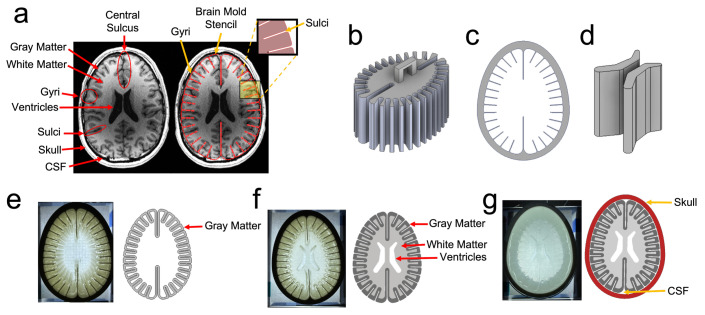
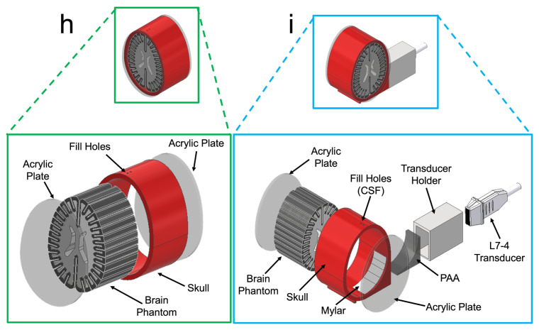
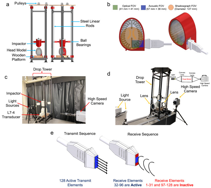
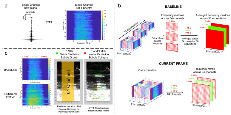
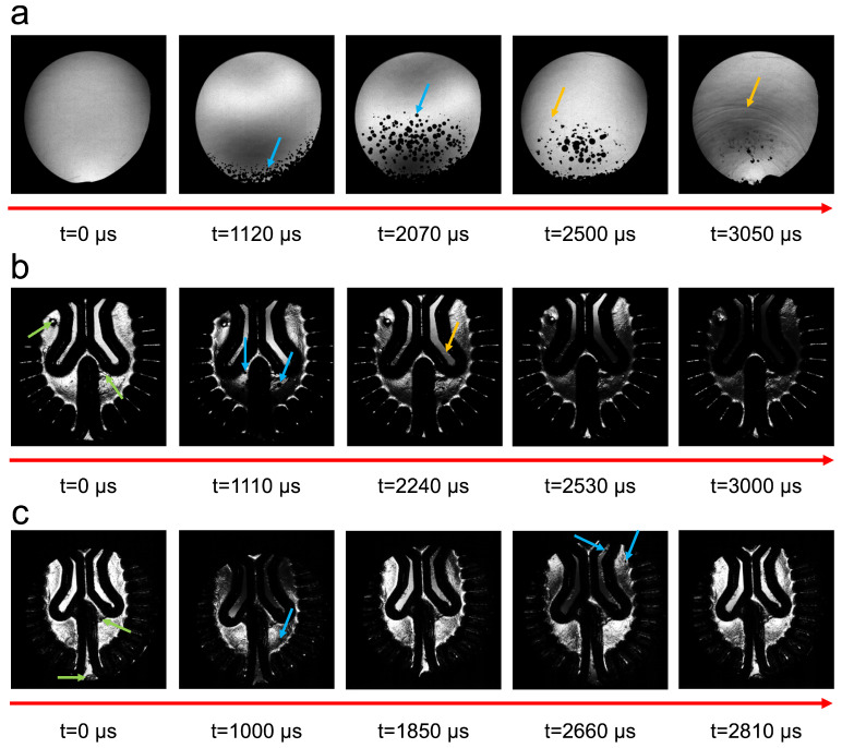
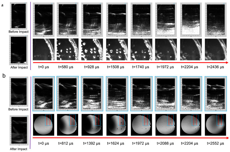
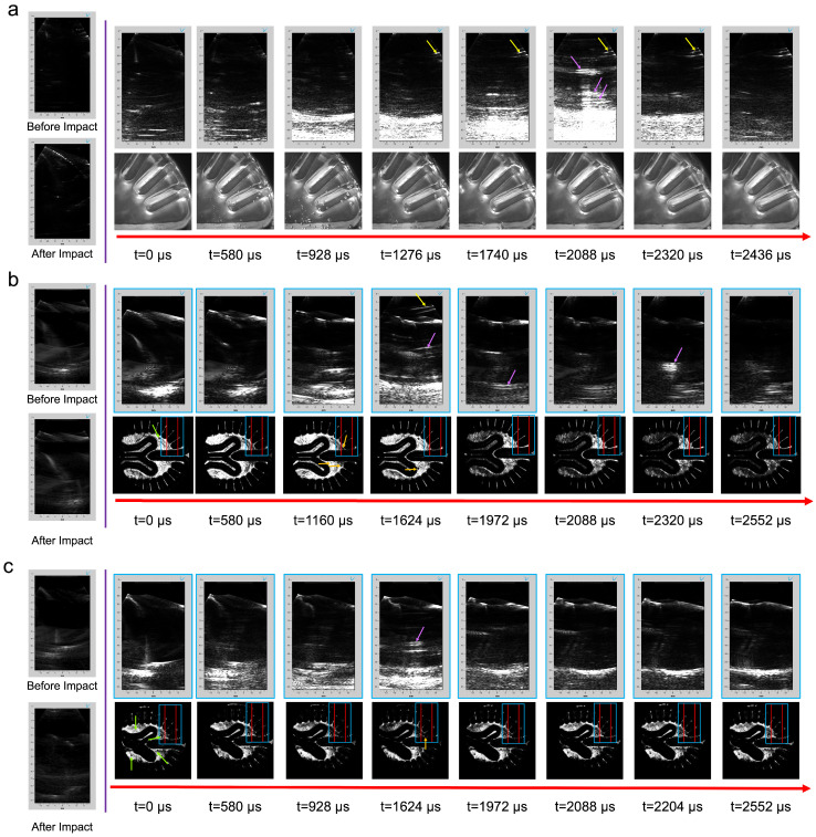
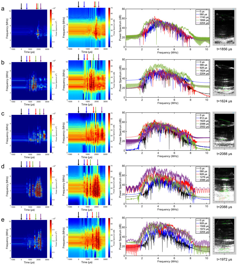
Blunt and blast impacts occur in civilian and military personnel, resulting in traumatic brain injuries necessitating a complete understanding of damage mechanisms and protective equipment design. However, the inability to monitor in vivo brain deformation and potential harmful cavitation events during collisions limits the investigation of injury mechanisms. To study the cavitation potential, we developed a full-scale human head phantom with features that allow a direct optical and acoustic observation at high frame rates during blunt impacts. The phantom consists of a transparent polyacrylamide material sealed with fluid in a 3D-printed skull where windows are integrated for data acquisition. The model has similar mechanical properties to brain tissue and includes simplified yet key anatomical features. Optical imaging indicated reproducible cavitation events above a threshold impact energy and localized cavitation to the fluid of the central sulcus, which appeared as high-intensity regions in acoustic images. An acoustic spectral analysis detected cavitation as harmonic and broadband signals that were mapped onto a reconstructed acoustic frame. Small bubbles trapped during phantom fabrication resulted in cavitation artifacts, which remain the largest challenge of the study. Ultimately, acoustic imaging demonstrated the potential to be a stand-alone tool, allowing observations at depth, where optical techniques are limited.

Keywords: cavitation; cranial phantoms; plane-wave imaging; polyacrylamide; shockwaves; traumatic brain injury (TBI).


Conflict of interest statement

The authors declare no conflicts of interest.

Figures

Figure 1
Figure 1
Design, fabrication, and assembly of the human head phantom. The geometrical basis for 3D-printed molds was a 2D transverse planar slice of the human head (a) revealing key anatomical features. The 3D-printed mold reveals the (b) white matter insert, (c) gray matter mold, and (d) ventricles. The pouring steps are portrayed by the (e) gray matter representation and the (f) combination of white and gray matter with a ventricular cavity. The assembly is displayed by the (g) PAA phantom sealed in the skull. Lastly, the two different skull geometries reveal the (h) original skull model and a (i) modified skull model with a transducer port.
Figure 1
Figure 1
Design, fabrication, and assembly of the human head phantom. The geometrical basis for 3D-printed molds was a 2D transverse planar slice of the human head (a) revealing key anatomical features. The 3D-printed mold reveals the (b) white matter insert, (c) gray matter mold, and (d) ventricles. The pouring steps are portrayed by the (e) gray matter representation and the (f) combination of white and gray matter with a ventricular cavity. The assembly is displayed by the (g) PAA phantom sealed in the skull. Lastly, the two different skull geometries reveal the (h) original skull model and a (i) modified skull model with a transducer port.
Figure 2
Figure 2
Schematic of the (a) drop tower assembly, (b) different fields of view for each imaging setup, (c) optical imaging in conjunction with acoustic imaging, (d) shadowgraph imaging, and (e) transmit and receive acoustic data acquisition sequence.
Figure 3
Figure 3
Cavitation mapping entailed the (a) creation of a spectral map by transforming the raw signal of a signal channel through Matlab’s built-in STFT function, (b) the fabrication of a baseline and comparison to a frame of interest by extracting data based on selected user-defined frequencies, and (c) a comparison of baseline and a selected acquisition for mapping potential regions of stable and inertial cavitation onto a reconstructed plane wave frame.
Figure 4
Figure 4
Shadowgraph imaging of head models illustrating cavitation bubble growth and collapse in the original skull geometry without an ultrasound port filled with (a) DI water (Video S2), (b) single-layered phantom (Video S3), and (c) a two-layered phantom (Video S4) all impacted with an impactor mass of 4 kg and a drop height of 60 cm. The green arrows display pre-existing bubbles before impact, the blue arrows represent areas of bubble growth, and the orange arrows reveal shockwave locations.
Figure 5
Figure 5
Acoustic and both optical and shadowgraph imaging timelines of head models incorporating a modified geometry to accommodate an ultrasound transducer filled with DI water impacted with an impactor mass of 4 kg and a drop height of 60 cm where one model (a) has more pre-existing bubbles (Video S5) compared to (b) a better sealing method (Video S6). The blue box corresponds to the 128-element transmit plane wave, while the area between the red lines correlates with the 64 receive elements.
Figure 6
Figure 6
Acoustic and optical imaging timelines of head models incorporating a modified geometry filled with an isotonic solution and a (a) two-layer PAA brain with an inadequate sealing method (Videos S7 and S8), (b) single-layer phantom, and (c) a two-layer phantom impacted with an impactor mass of 4 kg and a drop height of 60 cm. The blue box corresponds to the 128-element plane-wave transmission while the area between the red lines correlates with the 64 receive elements. Green arrows display areas of pre-existing defects in the PAA gel, while orange arrows represent areas of bubble growth. Yellow arrows display the reverberation in the PAA standoff pad, whereas magenta arrows highlight the reverberation generated from multiple bubbles within the head model.
Figure 7
Figure 7
Acoustic spectral analysis regarding a user-defined single channel linear and log power spectrograms, time-dependent logarithmic spectra, and cavitation mapping on a reconstructed frame. The following test involves a better sealing method and goes as follows: (a) channel 34 of a one-layer brain phantom, (b) channel 11 of a two-layered phantom, and (c) DI water. Both tests regarding (d) channel 47 of a two-layered phantom and (e) channel 24 of a DI water correspond to tests with a higher number of pre-existing bubbles.

Similar articles

References

    1. Barlow K.M. Traumatic brain injury. Handb. Clin. Neurol. 2013;112:891–904. doi: 10.1016/B978-0-444-52910-7.00011-8. - DOI - PubMed
    1. Blennow K., Brody D.L., Kochanek P.M., Levin H., McKee A., Ribbers G.M., Yaffe K., Zetterberg H. Traumatic brain injuries. Nat. Rev. Dis. Prim. 2016;2:1–19. doi: 10.1038/nrdp.2016.84. - DOI - PubMed
    1. Chapman J.C., Diaz-arrastia R. Military traumatic brain injury: A review. Alh. Dement. 2014;10:97–104. doi: 10.1016/j.jalz.2014.04.012. - DOI - PubMed
    1. Bryden D.W., Tilghman J.I., Hinds S.R. Blast-Related Traumatic Brain Injury: Current Concepts and Research Considerations. J. Exp. Neurosci. 2019;13:7–10. doi: 10.1177/1179069519872213. - DOI - PMC - PubMed
    1. Huh K.R., Kim J.Y., Choi S.H., Yoon Y.H., Park S.J., Lee E.S. Comparison of traumatic brain injury patients with brain computed tomography in the emergency department by age group. Clin. Exp. Emerg. Med. 2020;7:81–86. doi: 10.15441/ceem.19.076. - DOI - PMC - PubMed

LinkOut - more resources