. 2024 Feb 7;15(2):248.
doi: 10.3390/mi15020248.

Batch Fine Magnetic Pattern Transfer Method on Permanent Magnets Using Coercivity Change during Heating for Magnetic MEMS

Affiliations

Batch Fine Magnetic Pattern Transfer Method on Permanent Magnets Using Coercivity Change during Heating for Magnetic MEMS

Keita Nagai et al. Micromachines (Basel). .

Abstract

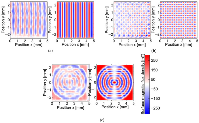
In magnetic microelectromechanical systems (MEMSs), permanent magnets in the form of a thick film or thin plate are used for structural and manufacturing purposes. However, the geometric shape induces a strong self-demagnetization field during thickness-direction magnetization, limiting the surface magnetic flux density and output power. The magnets must be segmented or magnetized in a fine and multi-pole manner to weaken the self-demagnetization field. Few studies have been performed on fine multi-pole magnetization techniques that can generate a higher surface magnetic flux density than segmented magnets and are suitable for mass production. This paper proposes a batch fine multi-pole magnetic pattern transfer (MPT) method for the magnets of MEMS devices. The proposed method uses two master magnets with identical magnetic patterns to sandwich a target magnet. Subsequently, the coercivity of the target magnet is reduced via heating, and the master magnet's magnetic pattern is transferred to the target magnet. Stripe, checkerboard, and concentric circle patterns with a pole pitch of 0.3 mm are magnetized on the NdFeB master magnets N38EH with high intrinsic coercivity via laser-assisted heating magnetization. The MPT yields the highest surface magnetic flux density at 160 °C, reaching 39.7-66.1% of the ideal magnetization pattern on the NdFeB target magnet N35.

Keywords: NdFeB magnet; laser-assisted heating; magnetic MEMS; magnetic pattern transfer; micromagnetization; multi-pole magnetization.


Conflict of interest statement

The authors declare no conflicts of interest.

Figures

Figure 1
Figure 1
Magnetic pattern transfer (MPT) method: (a) two master magnets with magnetic patterns and a target magnet unidirectionally magnetized in the thickness direction; (b) transfer procedure: Step 1: the target magnet is sandwiched between the two master magnets; step 2: these magnets are heated to reduce the coercivity of the target magnet. The magnetization of the intended region in the target magnet is then reversed by a transfer magnetic field consisting of the magnetic field of the master magnet and the leakage flux of the adjacent magnetic poles in the region where the magnetization reversal of the target magnet is intended; step 3: these magnets are cooled naturally, the coercivity of the target magnet is recovered, and the magnetic pattern transfer is achieved.
Figure 2
Figure 2
Segmentation of the magnet surface and laser scan trajectories for the magnetization condition search: (a) eight divided areas of the magnet; (b) the laser scan trajectories have four paths with a pitch of 0.6 mm in each segmented area, starting from the left end; (c) the magnetization pattern is eight poles in each area.
Figure 3
Figure 3
Uniform external magnetic field generated by multiple bulk NdFeB magnets in the out-of-plane direction to a master magnet sample: (a) 0.7 T; (b) 0.9 T.
Figure 4
Figure 4
Surface magnetic flux density measurement system consisting of a piezo-motor-driven linear stage scanning magnetized area over a magnet with a Hall probe and a 4-DOF micro stage to adjust the probe position and attitude: (a) photograph; (b) schematic.
Figure 5
Figure 5
Measured surface flux density distribution of an area magnetized on an N38EH magnet at a scanning speed of 150–160 mm/s.
Figure 6
Figure 6
Magnetization patterns of the master magnets.
Figure 7
Figure 7
Laser scan trajectories of each magnetization pattern for the master magnets.
Figure 8
Figure 8
Magnetic flux density measurement on the master magnet surface, continuous horizontal scanning of the Hall probe, and vertical positioning at a pitch of 0.3 mm.
Figure 9
Figure 9
Experimental setup and process of the MPT test: (a) experimental photo and configuration consisting of a hot plate, a steel block, and an aluminum container. (b) Experimental process: step 1: the surface temperature on the steel block is measured with a thermal camera; step 2: a target magnet sandwiched by two master magnets on the steel block is heated with an aluminum container; step 3: these magnets are removed from the hot plate and naturally cooled. (c) Calibration of emissivity and temperature: step 1: calibration of the emissivity of the thermal camera using a thermocouple placed on the surface of the steel block; step 2: determination of heating time by measuring the time required for the temperature inside the container to stabilize.
Figure 10
Figure 10
Magnetic flux density measurement on the target magnet surface, continuous horizontal scanning of the Hall probe, and vertical positioning at a pitch of 0.3 mm.
Figure 11
Figure 11
Experimental relationship between the scanning speed and the surface magnetic flux density p-p for the master magnet candidates.
Figure 12
Figure 12
Thermal stress simulation model of the LAH method: using a simple calculation by changing the timing of the heating area following the scanning speed: (a) the simulation model consists of three layers: a SmCo magnet, Kapton tape to fix the sample, and NdFeB to generate an external magnetic field; (b) top view of the model, divided into eight areas at the center; (c) time chart of laser heating in the area (1).
Figure 13
Figure 13
Average heating temperature and thermal stress with respect to the laser scanning speed: (a) relationship between the laser scanning speed and the average heating temperature; (b) relationship between the laser scanning speed and the thermal stress.
Figure 14
Figure 14
Surface magnetic flux density p-p and offset of the NdFeB magnet N38EH.
Figure 15
Figure 15
Surface magnetic flux density distribution of the master magnets: (a) stripe pattern; (b) checkerboard; (c) concentric circles.
Figure 16
Figure 16
Surface magnetic flux density distribution of the stripe pattern at each experimental temperature: (a) 100 °C; (b) 120 °C; (c) 140 °C; (d) 160 °C; (e) 180 °C; (f) 200 °C.
Figure 17
Figure 17
Surface magnetic flux density p-p for each experimental temperature.
Figure 18
Figure 18
Surface magnetic flux density distribution of the target magnets: (a) stripe pattern; (b) checkerboard; (c) concentric circles.
Figure 19
Figure 19
Relationship between the pole pitch and offset of the master magnet and its effect on the magnetization reversal pitch.
Figure 20
Figure 20
Simulation model for the transfer magnetic field calculation in the MPT method using a stripe pattern master magnet.
Figure 21
Figure 21
Measured magnetization curves of the target magnet using the TPM.
Figure 22
Figure 22
Relationships between the heating temperature and the measured intrinsic coercivity Hcj, magnetic field for the magnetic saturation Hsat, and the transfer magnetic field Htrans.

Similar articles

References

    1. Raeesi A., Al-Saedi H., Palizban A., Taeb A., Abdel-Wahab W.M., Gigoyan S., Safavi-Naeini S. Low-cost planar RF MEMS-based attenuator. IEEE MTT-S Int. Microw. Symp. Dig. 2019;2019:869–872.
    1. Nishibe Y., Nonomura Y., Tsukada K., Takeuchi M., Miyashita M., Ito K. Determination of engine misfiring using magnetoelastic torque sensor. IEEE Trans. Instrum. Meas. 1998;47:760–765. doi: 10.1109/19.744343. - DOI
    1. Niclass C., Ito K., Soga M., Matsubara H., Aoyagi I., Kato S., Kagami M. Design and characterization of a 256x64-pixel single-photon imager in CMOS for a MEMS-based laser scanning time-of-flight sensor. Opt. Express. 2012;20:11863–11881. doi: 10.1364/OE.20.011863. - DOI - PubMed
    1. Gao L., Xu X., Li S., Xu D., Yao Y. Micro acceleration measurement system based on highly-sensitive tunnel magneto-resistance sensor; Proceedings of the 2019 IEEE International Symposium on Inertial Sensors and Systems (INERTIAL); Naples, FL, USA. 1–5 April 2019; pp. 1–4. - DOI
    1. Ye L., Zhang G., You Z. Large-aperture kHz operating frequency Ti-alloy based optical micro scanning mirror for LiDAR application. Micromachines. 2017;8:120. doi: 10.3390/mi8040120. - DOI

LinkOut - more resources