. 2024 Jan 19;11(2):596-603.
doi: 10.1021/acsphotonics.3c01480. eCollection 2024 Feb 21.

Postfabrication Tuning of Circular Bragg Resonators for Enhanced Emitter-Cavity Coupling

Affiliations

Postfabrication Tuning of Circular Bragg Resonators for Enhanced Emitter-Cavity Coupling

Tobias M Krieger et al. ACS Photonics. .

Abstract

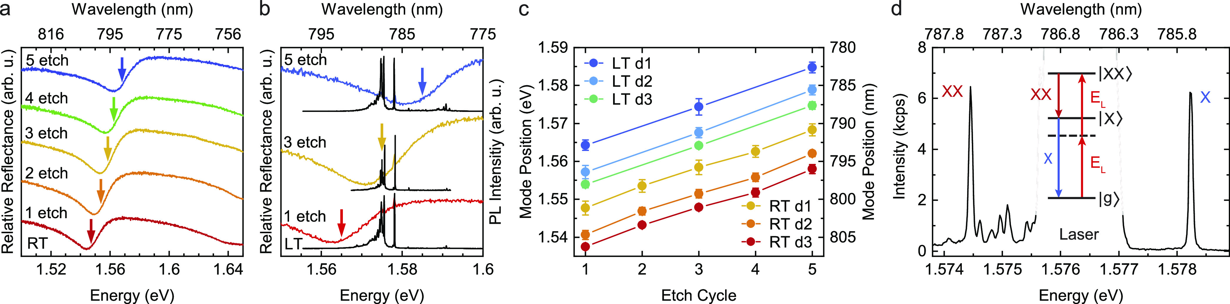
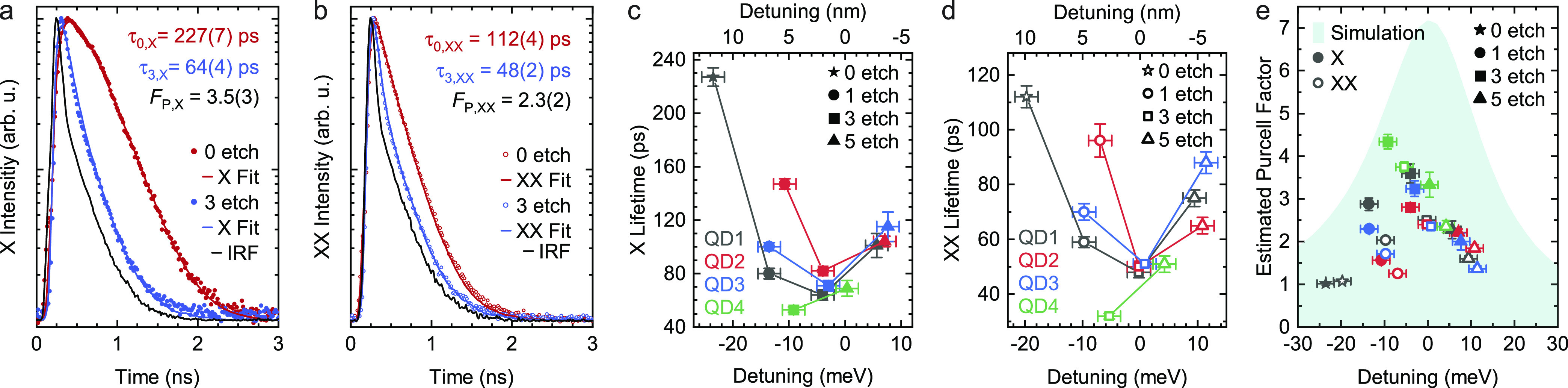
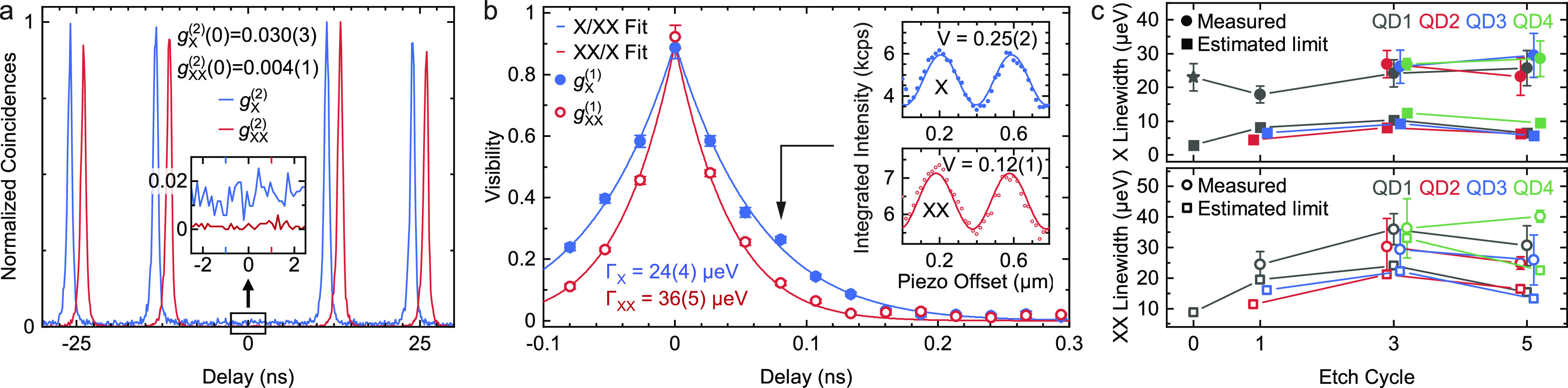
Solid-state quantum emitters embedded in circular Bragg resonators are attractive due to their ability to emit quantum light with high brightness and low multiphoton probability. As for any emitter-microcavity system, fabrication imperfections limit the spatial and spectral overlap of the emitter with the cavity mode, thus limiting their coupling strength. Here, we show that an initial spectral mismatch can be corrected after device fabrication by repeated wet chemical etching steps. We demonstrate an ∼16 nm wavelength tuning for optical modes in AlGaAs resonators on oxide, leading to a 4-fold Purcell enhancement of the emission of single embedded GaAs quantum dots. Numerical calculations reproduce the observations and suggest that the achievable performance of the resonator is only marginally affected in the explored tuning range. We expect the method to be applicable also to circular Bragg resonators based on other material platforms, thus increasing the device yield of cavity-enhanced solid-state quantum emitters.


Conflict of interest statement

The authors declare no competing financial interest.

Figures

Figure 1
Figure 1
(a) Sketch representing the CBR structure with geometric parameters before processing and the repeated removal of the native oxide by wet chemical etching. FDTD simulation results of the (b) Purcell enhancement, (c) extraction efficiency, and (d) CBR reflectance relative to that of the surrounding planar areas for repeated etch steps as a function of the photon energy and wavelength. (e) Reflectance curve fitted with a Fano line shape with marked resonance position Ec compared to the corresponding spectrum of the Purcell factor.
Figure 2
Figure 2
Relative reflectance spectra of a representative CBR, showing the etch-induced blue shift of the CM at (a) RT and (b) LT (colored curves). Resonance positions Ec are marked with an arrow. (b) also shows the PL spectrum (black curves) of the embedded QD obtained under above-bandgap excitation. (c) Mean values of Ec for 10 CBRs having the same nominal design (either d1, d2, or d3) at RT and LT as a function of the number of performed etch cycles. Error bars correspond to the standard deviation. (d) TPE spectrum with labeled X and XX transitions and the remaining excitation laser in the background. Inset: Level scheme of the |XX⟩ population and radiative cascade decay.
Figure 3
Figure 3
Time-correlated single-photon-counting measurements of X (a) and XX (b) photons emitted by QD1 upon TPE before (0 etch) and after 3 etch cycles. IRF denotes the instrument response function, and the quoted lifetimes clearly indicate a lifetime reduction, which we attribute to the Purcell effect. (c) Analysis of lifetime values as a function of detuning from the CM and different etch cycles for X and (d) XX. (e) Estimated Purcell factor as a function of detuning and simulated Purcell factor spectrum for a QD placed in the resonator center. (c–e) Different colors are used for different QDs, as labeled in (c,d), while full/empty symbols are used for X/XX photons. Error bars (vertical) of the estimated Purcell factor are based only on the uncertainty on the corresponding lifetime measurements. Error bars (horizontal) in the detuning axis are 2 meV, estimated experimentally from reflectance measurements. The detuning values of the star-data points were not directly measured but are estimations from the CM shift between etch cycles 0 and 1, measured using another CBR.
Figure 4
Figure 4
(a) g(2)(t) autocorrelation and (b) g(1)(t) coherence measurements of X (blue line) and XX (red line) photons for QD1 after (a) 5 and (b) 3 etch cycles. (a) XX/X peaks are horizontally shifted by ±1 ns for ease of reading. (b) Insets show X and XX interference fringes at a 80 ps time delay. (c) X (full/solid) and XX (empty/dashed) transition line width values of the studied QDs for different etch cycles comparing measured line widths (circle) to the expected natural line widths (square) based on the respective lifetimes. The star-data point was obtained under nonresonant excitation.

References

    1. Kimble H. J. The quantum internet. Nature 2008, 453, 1023–1030. 10.1038/nature07127. - DOI - PubMed
    1. Gisin N.; Thew R. Quantum communication. Nat. Photonics 2007, 1, 165–171. 10.1038/nphoton.2007.22. - DOI
    1. Fedrizzi A.; Ursin R.; Herbst T.; Nespoli M.; Prevedel R.; Scheidl T.; Tiefenbacher F.; Jennewein T.; Zeilinger A. High-fidelity transmission of entanglement over a high-loss free-space channel. Nat. Phys. 2009, 5, 389–392. 10.1038/nphys1255. - DOI
    1. Meyer-Scott E.; Silberhorn C.; Migdall A. Single-photon sources: Approaching the ideal through multiplexing. Rev. Sci. Instrum. 2020, 91, 041101.10.1063/5.0003320. - DOI - PMC - PubMed
    1. Orieux A.; Versteegh M. A. M.; Jöns K. D.; Ducci S. Semiconductor devices for entangled photon pair generation: a review. Rep. Prog. Phys. 2017, 80, 076001.10.1088/1361-6633/aa6955. - DOI - PubMed

LinkOut - more resources