. 2024 Mar;627(8004):505-509.
doi: 10.1038/s41586-023-06998-2. Epub 2024 Feb 28.

The Dimorphos ejecta plume properties revealed by LICIACube

Affiliations

The Dimorphos ejecta plume properties revealed by LICIACube

E Dotto et al. Nature. 2024 Mar.

Abstract

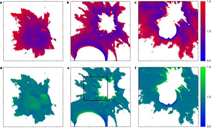
The Double Asteroid Redirection Test (DART) had an impact with Dimorphos (a satellite of the asteroid Didymos) on 26 September 20221. Ground-based observations showed that the Didymos system brightened by a factor of 8.3 after the impact because of ejecta, returning to the pre-impact brightness 23.7 days afterwards2. Hubble Space Telescope observations made from 15 minutes after impact to 18.5 days after, with a spatial resolution of 2.1 kilometres per pixel, showed a complex evolution of the ejecta3, consistent with other asteroid impact events. The momentum enhancement factor, determined using the measured binary period change4, ranges between 2.2 and 4.9, depending on the assumptions about the mass and density of Dimorphos5. Here we report observations from the LUKE and LEIA instruments on the LICIACube cube satellite, which was deployed 15 days in advance of the impact of DART. Data were taken from 71 seconds before the impact until 320 seconds afterwards. The ejecta plume was a cone with an aperture angle of 140 ± 4 degrees. The inner region of the plume was blue, becoming redder with increasing distance from Dimorphos. The ejecta plume exhibited a complex and inhomogeneous structure, characterized by filaments, dust grains and single or clustered boulders. The ejecta velocities ranged from a few tens of metres per second to about 500 metres per second.


Conflict of interest statement

The authors declare no competing interests.

Figures

Fig. 1
Fig. 1. The viewing geometry of LICIACube.
ae, Schematic of the DART impact and LICIACube viewing geometries (a) and cropped images of Didymos and Dimorphos as seen by LEIA (b,c) and LUKE (d,e). a, The trajectory and the footprint on Didymos are shown in green; ĥ is the positive pole direction of Didymos; the red arrow is the incident direction of the DART; Ê is the cone axis pointing; the relative direction of the Sun is also shown in yellow. b, The binary system imaged at a distance of approximately 1,000 km, 5 s before the impact: Didymos is visible in the centre of the LEIA FOV and Dimorphos appears as a ring (because of the de-focusing of the instrument, discovered on flight) at the lower right side of Didymos. c, The same scene viewed 1 s after the impact: the expanding ejecta plume causes an increase of a factor 5, in terms of DN over the same area in the lower right side of Didymos. d, RGB image of the targets acquired at a distance of 76 km, 8.5 s before CA (159 s after impact). e, RGB image at a distance of 71 km, 6.5 s after CA (174 s after impact). Scale bars, 500 m (d,e).
Fig. 2
Fig. 2. Identification and orientation of the filamentary streams.
The directions of the streams are computed as they extend from the surface of Dimorphos. a, Filaments are superimposed onto a LUKE RGB composition of the image triplet obtained at 2022-09-26T23:16:58.916, T + 154 s. The spatial resolution of the image is 7.5 m per pixel at 97 km from Dimorphos. The filaments are counted at projected distances higher than 230 m from the photocentre of the ejecta. The frame has been rotated and recentred with respect to Dimorphos. Dimorphos is saturated and Didymos has been masked. Scale bar, 0.5 km. b, Supporting synthetic frame with the binary system and the filaments superimposed onto the RA/DEC sky plane (green grid). DART, incoming DART spacecraft vector; SUN, solar vector; EARTH, vector of Earth; POLE, Didymos system rotation pole vector; NCP, North equatorial celestial pole vector. Shape models of Didymos and Dimorphos from ref.  and ref. , respectively. c, Angular orientation of the filaments with respect to DART incoming velocity vector in the RA/DEC sky plane.
Fig. 3
Fig. 3. Measured ejection velocities of some morphological features in the ejecta plume.
Many complex structures can be noted (see the full list in Extended Data Table 2): the two arm-like streams arising from F5/F6 and F14/F15 (identified in Fig. 2); resolved detached structures, named clumps (C); bright punctiform-like unresolved features, named nodules (N); filament breaking, merging, discontinuities and undulations (B). a, Frame obtained 106 s after the impact superimposed with the projected displacement measured between two frames (black lines). b, Frame obtained 118 s after the impact superimposed with the two solutions for FOV-corrected magnitude velocities (blue and green vectors, respectively, see Methods). c, Orientation and projected velocities in the RA/DEC sky plane and angle with respect to the DART incoming velocity vector. d, RGB composition of LUKE triplet images obtained 118 s after the impact. The spatial resolution of the image is 23 m per pixel at 304 km from Dimorphos. All the frames have been rotated and recentred with respect to Dimorphos. Didymos and Dimorphos are saturated. Scale bars, 5 km (a,b,d).
Fig. 4
Fig. 4. Flux ratios in LUKE colour filter data for image triplet.
af, Images with different exposure times (nominally 0.5 ms for a and d, 4 ms for b and e, and 20 ms for c and f). The colour bars are the red:blue (ac) and the green:blue (df) ratios. The black rectangle in e highlights specific details of the plume structure with visible streams characterized by a green colour over the average blue colour of the inner part of the plume (see the text for details).
Extended Data Fig. 1
Extended Data Fig. 1. The ejecta curtain as seen by LICIACube.
The cropped parts of images that were used for the analysis. The red lines in panels 1–5 indicate the slant axes of the ejecta cone that were used to measure the projected aperture angle 2δ. Panel 6 shows the ejecta cone in a different geometry than those in panels 1–5, which was used as a discriminator when accepting or rejecting candidate solutions for the ejecta cone. Image IDs correspond to those given in Extended Data Table 1.
Extended Data Fig. 2
Extended Data Fig. 2. The ejecta cone geometry.
A perfectly axisymmetric cone and its projection onto a plane which gives the relation between the original cone aperture angle and the aperture angle of the projected cone given in Eq. (1). In the plot, the original cone is sliced perpendicularly to its axis. On the slice, the centre along the cone axis is defined as A, and the intersections of the two orthogonal axes with the cone shell are also denoted as P, Q, R, and S. Their projected points on the plane are given using subscript 1.
Extended Data Fig. 3
Extended Data Fig. 3. Ejecta cone orientation.
The blue curve, obtained by matching the position angle of the ejecta cone in image ID1, corresponds to the solutions of the ejecta cone axis direction that are mathematically possible. The yellow dot indicates our solution of RA, DEC: 137°, + 19° constrained by comparing the simulated ejecta cones with the LUKE images in Extended Data Fig. 1 and its uncertainty region is illustrated by the transparent purple circle. DART incoming direction (just before the impact) of RA, DEC: 127°, + 18° and the impact point at RA, DEC: 143°, + 12° are given as references.
Extended Data Fig. 4
Extended Data Fig. 4. The shape of Dimorphos.
The two pairs of images used to identify the illuminated and non-illuminated hemispheres of Dimorphos and compute the size. Images at frames (a) liciacube_luke_l2_1664234241_00417_01 and (c) liciacube_luke_l2_1664234244_00417_01 have an exposure time of 0.035 s; images at frame (b) liciacube_luke_l2_1664234241_00007_01 and d (liciacube_luke_l2_1664234244_00007_01) of 0.0007 s. The red shape in (a) and (c) identifies the non illuminated hemisphere (with areas of 5330 and 5320 m2, respectively and accuracy of 60 m2), whereas the cyan shape in b and d identifies the illuminated one (with areas of 3100 and 2220 m2, respectively and accuracy of 200 m2). A “dark arc” is evident between this shape and the plume. A1 and A2 in image (a) indicate the two axes identified and described in the text.
Extended Data Fig. 5
Extended Data Fig. 5. The early resolved ejected structures.
(a) Scheme of the Pythagorean solution for the projection-correction of ejecta velocity assuming that the projection angle ω is virtually the same for the two frames taken at short time difference and large observer distance to the ejecta structure, which is displacing from its origin at the time of the impact. The scales are exaggerated for better visualisation. The labels are: O – origin, k – frame index; S – spacecraft position; P – Position of the ejecta structure; Pj – structure extension projected to frame; D – distance from spacecraft to origin; θ – angular distance to of structure to origin measured from spacecraft; σ – distance between origin and projection Pj on the frame plane. (b,c,d) Velocities from early resolved ejected structures from the pair of LUKE frames obtained 34 and 46 s after the impact. (b): 34-seconds-after frame is superimposed with the measured projected displacements in black. (c): 46-seconds-after frame is superimposed with the FOV-corrected velocity magnitudes in green. (d): The orientation and projected velocity magnitudes in the RA/DEC sky plane with respect to the DART incoming velocity vector. The frame has been rotated and recentered with respect to Dimorphos. Didymos and Dimorphos are saturated.
Extended Data Fig. 6
Extended Data Fig. 6. Signal to Noise values for RGB channels in LUKE images.
The showed S/N have been evaluated from background of images acquired at time 2022-09-26T23:17:03.000Z (0.5 ms exposure time, SCLK 1664234223), 2022-09-26T23:17:03.004Z (4 ms exposure time), and 2022-09-26T23:17:03.024Z (20 ms exposure time).
Extended Data Fig. 7
Extended Data Fig. 7. Didymos-Dimorphos maps of flux ratio in LUKE colour filter data.
Flux ratio (panel A, top) and fluxes ratio error (panel B, bottom) for LUKE images at different exposure times (see RGB analysis method text for reference). From the top row to the bottom: red over blue ratio, red over green ratio and green over blue ratio.

References

    1. Daly RT, et al. Successful kinetic impact into an asteroid for planetary defence. Nature. 2023;616:443–447. doi: 10.1038/s41586-023-05810-5. - DOI - PMC - PubMed
    1. Graykowski A, et al. Light curves and colours of the ejecta from Dimorphos after the DART impact. Nature. 2023;616:461–464. doi: 10.1038/s41586-023-05852-9. - DOI - PMC - PubMed
    1. Li J-Y, et al. Ejecta from the DART-produced active asteroid Dimorphos. Nature. 2023;616:452–456. doi: 10.1038/s41586-023-05811-4. - DOI - PMC - PubMed
    1. Thomas CA, et al. Orbital period change of Dimorphos due to the DART kinetic impact. Nature. 2023;616:448–451. doi: 10.1038/s41586-023-05805-2. - DOI - PMC - PubMed
    1. Cheng AF, et al. Momentum transfer from the DART mission kinetic impact on asteroid Dimorphos. Nature. 2023;616:457–460. doi: 10.1038/s41586-023-05878-z. - DOI - PMC - PubMed