

A Taxonomy for Three-Terminal Tandem Solar Cells
- PMID: 38435798
- PMCID: PMC10906945
- DOI: 10.1021/acsenergylett.0c00068
A Taxonomy for Three-Terminal Tandem Solar Cells
Abstract
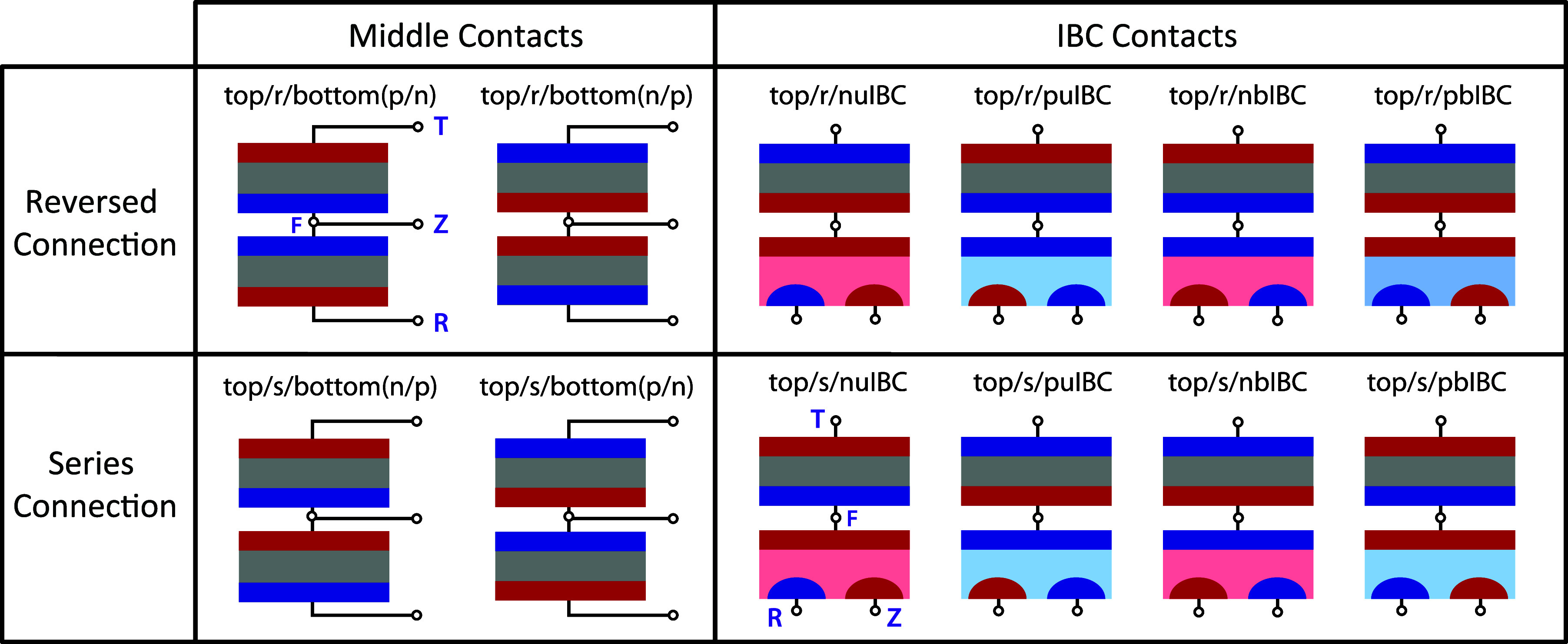
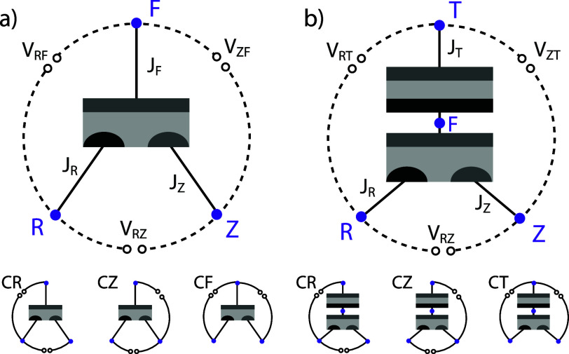
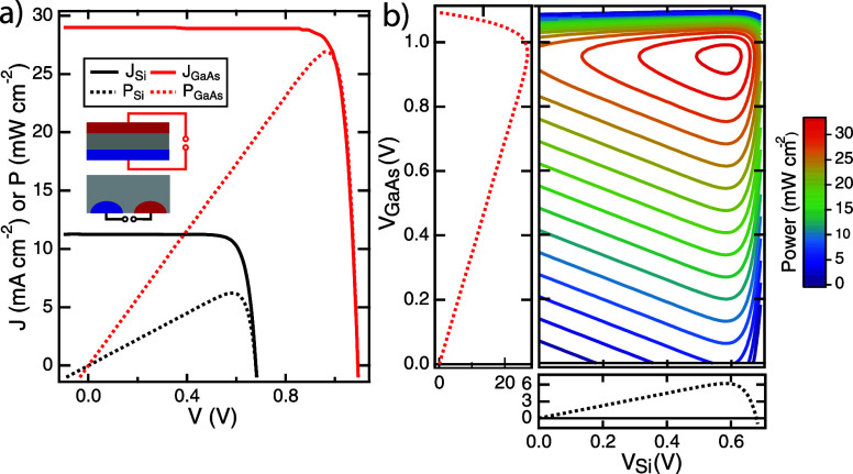
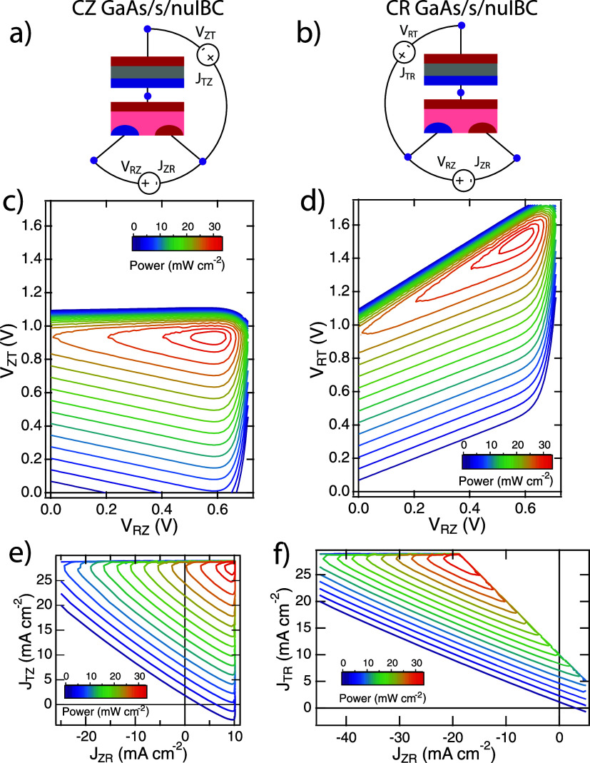
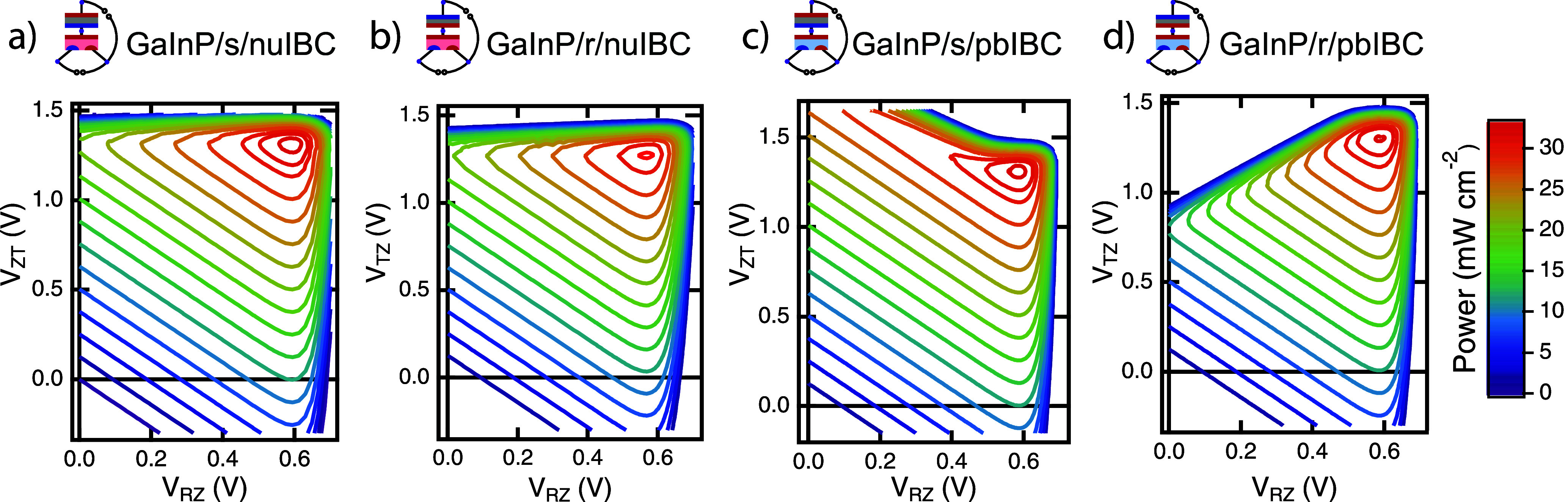
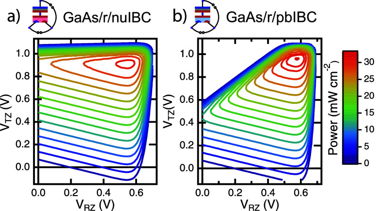
Tandem and multijunction solar cells offer the only demonstrated path to terrestrial 1-sun solar cell efficiency over 30%. Three-terminal tandem (3TT) solar cells can overcome some of the limitations of two-terminal and four-terminal tandem solar cell designs. However, the coupled nature of the cells adds a degree of complexity to the devices themselves and the ways that their performance can be measured and reported. While many different configurations of 3TT devices have been proposed, there is no standard taxonomy to discuss the device structure or loading topology. This Perspective proposes a taxonomy for 3TT solar cells to enable a common nomenclature for discussing these devices and their performance. It also provides a brief history of three-terminal devices in the literature and demonstrates that many different 3TT devices can work at efficiencies above 30% if properly designed.
Conflict of interest statement
The authors declare no competing financial interest.
Figures
References
-
- Essig S.; Allebé C.; Remo T.; Geisz J. F.; Steiner M. A.; Horowitz K.; Barraud L.; Ward J. S.; Schnabel M.; Descoeudres A.; Young D. L.; Woodhouse M.; Despeisse M.; Ballif C.; Tamboli A. Raising the one-sun conversion efficiency of III–V/Si solar cells to 32.8% for two junctions and 35.9% for three junctions. Nature Energy 2017, 2, 17144.10.1038/nenergy.2017.144. - DOI
-
- Yamaguchi M.; Lee K.-H.; Araki K.; Kojima N. A review of recent progress in heterogeneous silicon tandem solar cells. J. Phys. D: Appl. Phys. 2018, 51, 133002.10.1088/1361-6463/aaaf08. - DOI
-
- Warren E. L.; Deceglie M. G.; Rienäcker M.; Peibst R.; Tamboli A. C.; Stradins P. Maximizing tandem solar cell power extraction using a three-terminal design. Sustainable Energy & Fuels 2018, 2, 1141–1147. 10.1039/C8SE00133B. - DOI
-
- Nagashima T.; Okumura K.; Murata K.; Kimura Y. Three-terminal tandem solar cells with a back-contact type bottom cell. Proceedings of the 28th IEEE PVSC 2000, 1193–1196. 10.1109/PVSC.2000.916102. - DOI
-
- Rienäcker M.; Warren E. L.; Schnabel M.; Schulte-Huxel H.; Niepelt R.; Brendel R.; Stradins P.; Tamboli A. C.; Peibst R. Back-contacted bottom cells with three terminals: Maximizing power extraction from current-mismatched tandem cells. Prog. Photovoltaics 2019, 27, 410–423. 10.1002/pip.3107. - DOI
Publication types
LinkOut - more resources
Full Text Sources
Other Literature Sources