. 2024 Mar;627(8004):540-545.
doi: 10.1038/s41586-024-07057-0. Epub 2024 Mar 6.

Integrated optical frequency division for microwave and mmWave generation

Affiliations

Integrated optical frequency division for microwave and mmWave generation

Shuman Sun et al. Nature. 2024 Mar.

Abstract

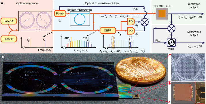
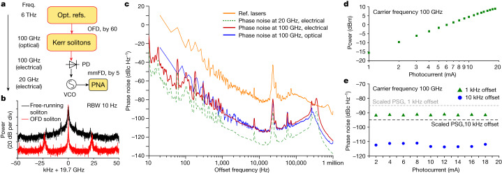
The generation of ultra-low-noise microwave and mmWave in miniaturized, chip-based platforms can transform communication, radar and sensing systems1-3. Optical frequency division that leverages optical references and optical frequency combs has emerged as a powerful technique to generate microwaves with superior spectral purity than any other approaches4-7. Here we demonstrate a miniaturized optical frequency division system that can potentially transfer the approach to a complementary metal-oxide-semiconductor-compatible integrated photonic platform. Phase stability is provided by a large mode volume, planar-waveguide-based optical reference coil cavity8,9 and is divided down from optical to mmWave frequency by using soliton microcombs generated in a waveguide-coupled microresonator10-12. Besides achieving record-low phase noise for integrated photonic mmWave oscillators, these devices can be heterogeneously integrated with semiconductor lasers, amplifiers and photodiodes, holding the potential of large-volume, low-cost manufacturing for fundamental and mass-market applications13.


Conflict of interest statement

The authors declare no competing interests.

Figures

Fig. 1
Fig. 1. Conceptual illustration of integrated OFD.
a, Simplified schematic. A pair of lasers that are stabilized to an integrated coil reference cavity serve as the optical references and provide phase stability for the mmWave and microwave oscillator. The relative frequency difference of the two reference lasers is then divided down to the repetition rate of a soliton microcomb by feedback control of the frequency of the laser that pumps the soliton. A high-power, low-noise mmWave is generated by photodetecting the OFD soliton microcomb on a CC-MUTC PD. The mmWave can be further divided down to microwave through a mmWave to microwave frequency division with a division ratio of M. PLL, phase lock loop. b, Photograph of critical elements in the integrated OFD. From left to right are: a SiN 4 m long coil waveguide cavity as an optical reference, a SiN chip with tens of waveguide-coupled ring microresonators to generate soliton microcombs, a flip-chip bonded CC-MUTC PD for mmWave generation and a US 1-cent coin for size comparison. Microscopic pictures of a SiN ring resonator and a CC-MUTC PD are shown on the right. Scale bars, 100 μm (top and bottom left), 50 μm (bottom right).
Fig. 2
Fig. 2. Experimental setup.
A pair of reference lasers is created by stabilizing frequencies of lasers A and B to a SiN coil waveguide reference cavity, which is temperature controlled by a thermoelectric cooler (TEC). Soliton microcomb is generated in an integrated SiN microresonator. The pump laser is the first modulation sideband of a modulated continuous wave laser, and the sideband frequency can be rapidly tuned by a VCO. To implement two-point locking for OFD, the 0th comb line (pump laser) is photomixed with reference laser A, while the –Nth comb line is photomixed with reference laser B. The two photocurrents are then subtracted on an electrical mixer to yield the phase difference between the reference lasers and N times the soliton repetition rate, which is then used to servo control the soliton repetition rate by controlling the frequency of the pump laser. The phase noise of the reference lasers and the soliton repetition rate can be measured in the optical domain by using dual-tone delayed self-heterodyne interferometry. Low-noise, high-power mmWaves are generated by detecting soliton microcombs on a CC-MUTC PD. To characterize the mmWave phase noise, a mmWave to  microwave frequency division is implemented to stabilize a 20 GHz VCO to the 100 GHz mmWave and the phase noise of the VCO can be directly measured by a phase noise analyser (PNA). Erbium-doped fibre amplifiers (EDFAs), polarization controllers (PCs), phase modulators (PMs), single-sideband modulator (SSB-SC), band pass filters (BPFs), fibre-Bragg grating (FBG) filters, line-by-line waveshaper (WS), acoustic-optics modulator (AOM), electrical amplifiers (Amps) and a source meter (SM) are also used in the experiment.
Fig. 3
Fig. 3. OFD characterization.
a, Optical spectra of soliton microcombs (blue) and reference (Ref.) lasers corresponding to different division ratios. b, Phase noise of the frequency difference between the two reference lasers stabilized to coil cavity (orange) and the two lasers at free running (blue). The black dashed line shows the thermal refractive noise (TRN) limit of the reference cavity. c, Phase noise of reference lasers (orange), the repetition rate of free-running soliton microcombs (light blue), soliton repetition rate after OFD with a division ratio of 60 (blue) and the projected repetition rate with 60 division ratio (red). d, Soliton repetition rate phase noise at 1 and 10 kHz offset frequencies versus OFD division ratio. The projections of OFD are shown with coloured dashed lines.
Fig. 4
Fig. 4. Electrical domain characterization of mmWaves generated from integrated OFD.
a, Simplified schematic of frequency division. The 100 GHz mmWave generated by integrated OFD is further divided down to 20 GHz for phase noise characterization. b, Typical electrical spectra of the VCO after mmWave to microwave frequency division. The VCO is phase stabilized to the mmWave generated with the OFD soliton (red) or free-running soliton (black). To compare the two spectra, the peaks of the two traces are aligned in the figure. RBW, resolution bandwidth. c, Phase noise measurement in the electrical domain. Phase noise of the VCO after mmFD is directly measured by the phase noise analyser (dashed green). Scaling this trace to a carrier frequency of 100 GHz yields the phase noise upper bound of the 100 GHz mmWave (red). For comparison, phase noises of reference lasers (orange) and the OFD soliton repetition rate (blue) measured in the optical domain are shown. d, Measured mmWave power versus PD photocurrent at −2 V bias. A maximum mmWave power of 9 dBm is recorded. e, Measured mmWave phase noise at 1 and 10 kHz offset frequencies versus PD photocurrent.

References

    1. Koenig S, et al. Wireless sub-THz communication system with high data rate. Nat. Photonics. 2013;7:977–981. doi: 10.1038/nphoton.2013.275. - DOI
    1. Ghelfi P, et al. A fully photonics-based coherent radar system. Nature. 2014;507:341–345. doi: 10.1038/nature13078. - DOI - PubMed
    1. Long, D. & Ulaby, F. Microwave Radar and Radiometric Remote Sensing (Artech, 2015).
    1. Fortier TM, et al. Generation of ultrastable microwaves via optical frequency division. Nat. Photonics. 2011;5:425–429. doi: 10.1038/nphoton.2011.121. - DOI
    1. Xie X, et al. Photonic microwave signals with zeptosecond-level absolute timing noise. Nat. Photonics. 2017;11:44–47. doi: 10.1038/nphoton.2016.215. - DOI