

Analysis of Flow Through Extra-Anatomic Bypasses Between Supra-Aortic Branches Using Particle Image Velocimetry (PIV)
- PMID: 38449712
- PMCID: PMC10916461
- DOI: 10.1177/11795468231221413
Analysis of Flow Through Extra-Anatomic Bypasses Between Supra-Aortic Branches Using Particle Image Velocimetry (PIV)
Abstract
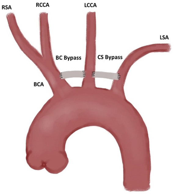
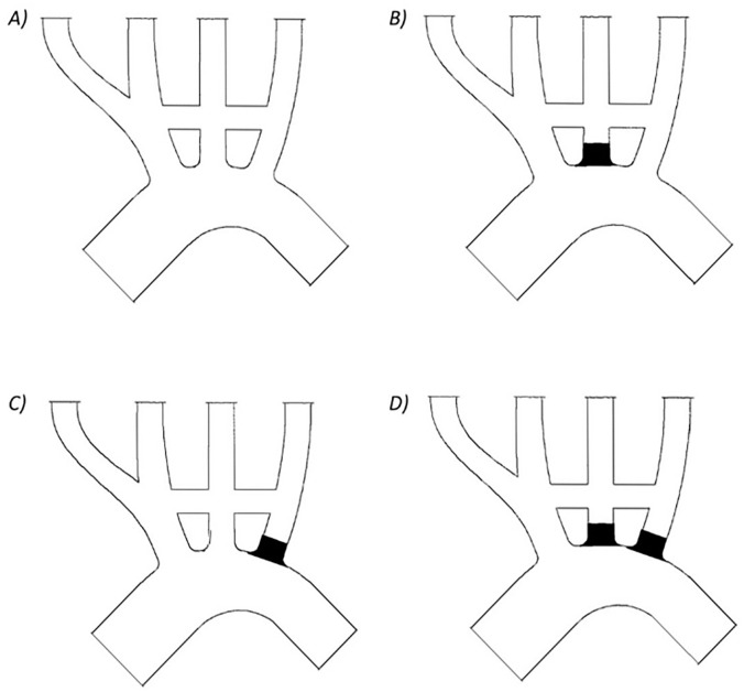
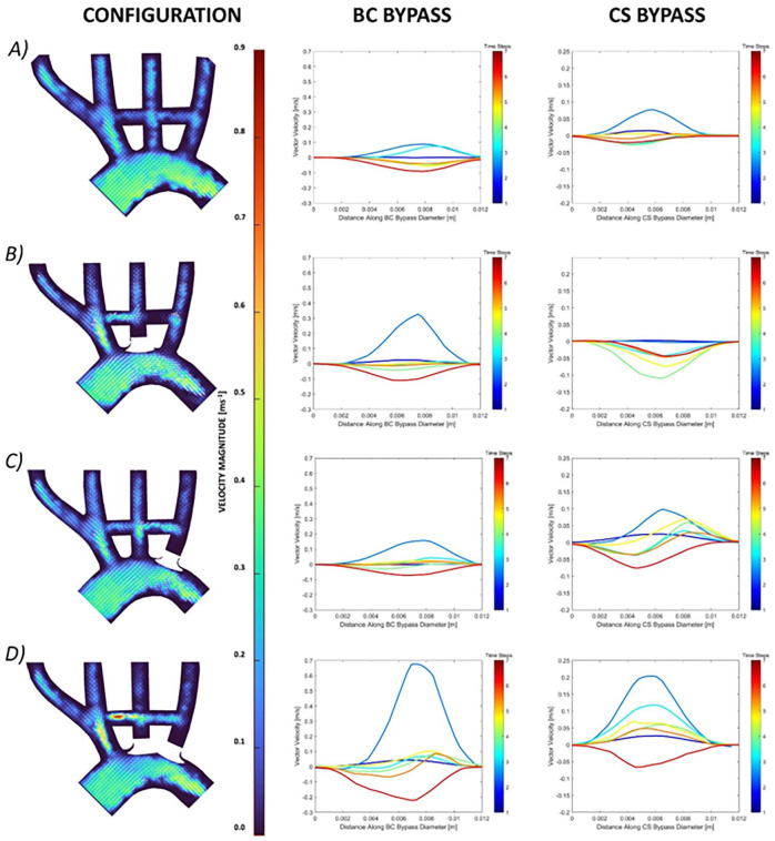
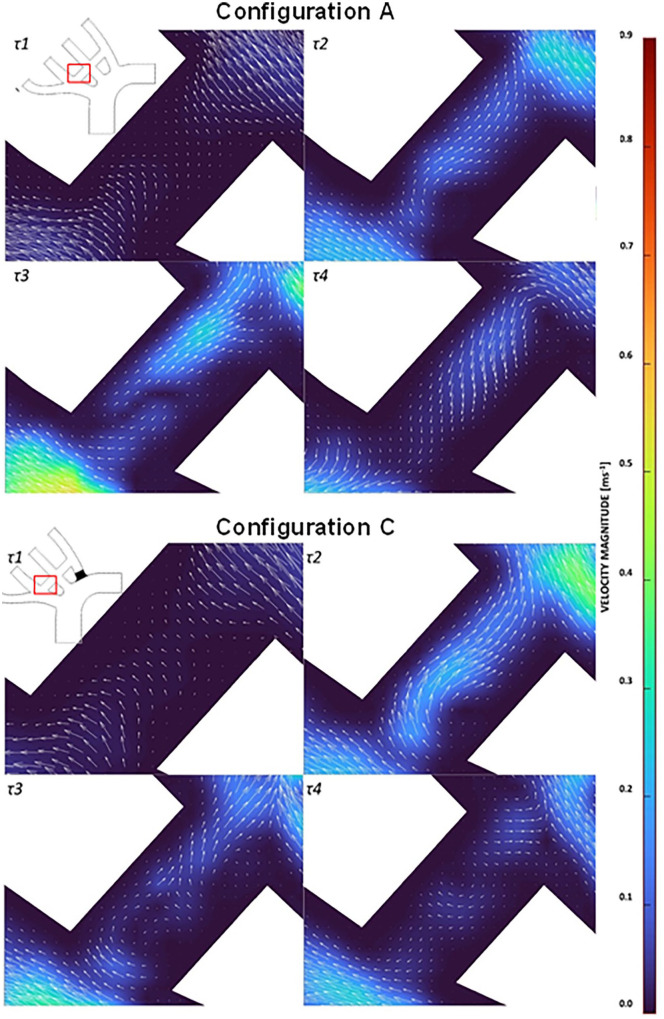
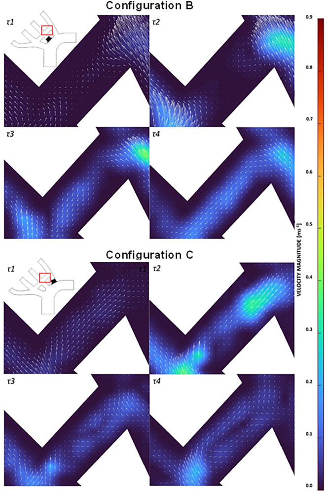
Supra-aortic extra-anatomic debranch (SAD) are prosthetic surgical grafts used to revascularize head and neck arteries that would be blocked during a surgical or hybrid procedure used in treating ascending and arch of the aorta pathologies. However, bypassing the supra-aortic arteries but not occluding their orifice might introduce potential for competitive flow that reduces bypass patency. Competitive flow within the bypasses across the supra-aortic arteries has not previously been identified. This research identified haemodynamics due to prophylactic inclusion of bypasses from the brachiocephalic artery (BCA) to the left common carotid artery (LCCA), and from the LCCA to left subclavian artery (LSA). Four model configurations investigated the risk of competitive flow and the necessity of intentionally blocking the proximal LSA and/or LCCA. Particle image velocimetry (PIV) was used to assess haemodynamics in each model configuration. We found potential for competitive flow in the BCA-LCCA bypass when the LSA was blocked, in the LSA-LCCA bypass, when the LCCA alone or LCCA and LSA were blocked. Flow stagnated at the start of systole within the RCCA-LCCA bypass, along with notable recirculation zones and reciprocating flow occurring throughout systolic flow. Flow also stagnated in the LCCA-LSA bypass when the LCCA was blocked. There was a large recirculation in the LCCA-LSA bypass when both the LCCA and LSA were blocked. The presence of competitive flow in all other configurations indicated that it is necessary to block or ligate the native LCCA and LSA once the debranch is made and the thoracic endovascular aortic repair (TEVAR) completed.
Keywords: Cardiovascular surgery; debranching; haemodynamic modelling; particle image velocimetry.
© The Author(s) 2024.
Conflict of interest statement
The author(s) declared no potential conflicts of interest with respect to the research, authorship, and/or publication of this article.
Figures
Similar articles
-
Applicability of a standardized thoracic endograft with a single branch for the left subclavian artery to treat aortic disease involving the distal arch.J Vasc Surg. 2020 Nov;72(5):1516-1523. doi: 10.1016/j.jvs.2020.02.011. Epub 2020 Apr 6. J Vasc Surg. 2020. PMID: 32273223
-
Aortic Arch Anatomy Pattern in Patients Treated Using Double Homemade Fenestrated Stent-Grafts for Total Endovascular Aortic Arch Repair.J Endovasc Ther. 2020 Oct;27(5):785-791. doi: 10.1177/1526602820931787. Epub 2020 Jun 4. J Endovasc Ther. 2020. PMID: 32495679
-
The single-centre experience of the supra-arch chimney technique in endovascular repair of type B aortic dissections.Eur J Vasc Endovasc Surg. 2013 Jun;45(6):633-8. doi: 10.1016/j.ejvs.2013.02.016. Epub 2013 Mar 27. Eur J Vasc Endovasc Surg. 2013. PMID: 23540806
-
Should intentional endovascular stent-graft coverage of the left subclavian artery be preceded by prophylactic revascularisation?Eur J Cardiothorac Surg. 2011 Oct;40(4):858-68. doi: 10.1016/j.ejcts.2011.01.046. Epub 2011 Mar 3. Eur J Cardiothorac Surg. 2011. PMID: 21376612 Review.
-
Anatomic Utility of Single Branched Thoracic Endograft During Thoracic Endovascular Aortic Repair.Vasc Endovascular Surg. 2023 Oct;57(7):680-688. doi: 10.1177/15385744231165988. Epub 2023 Mar 24. Vasc Endovascular Surg. 2023. PMID: 36961838 Review.
References
-
- Singh C, Wang X, Morsi Y, Wong C. Importance of stent-graft design for aortic arch aneurysm repair. AIMS Bioeng. 2017;4:133-150.
-
- Xydas S, Wei B, Takayama H, et al.. Use of carotid-subclavian arterial bypass and thoracic endovascular aortic repair to minimize cerebral ischemia in total aortic arch reconstruction. J Thorac Cardiovasc Surg. 2010;139:717-722. - PubMed
-
- Feezor RJ, Lee WA. Management of the left subclavian artery during TEVAR. Semin Vasc Surg. 2009;22:159-164. - PubMed
-
- Caro CG. ed. The Mechanics of the Circulation. 2nd ed. Cambridge University Press; 2012.
-
- Kamman AV, Eliason JL, Williams DM, et al.. Impact of left subclavian artery revascularization before thoracic endovascular aortic repair on postoperative cerebrovascular hemodynamics. Ann Vasc Surg. 2018;46:307-313. - PubMed
LinkOut - more resources
Full Text Sources
