

A prototype scintillator real-time beam monitor for ultra-high dose rate radiotherapy
- PMID: 38456622
- PMCID: PMC11992679
- DOI: 10.1002/mp.17018
A prototype scintillator real-time beam monitor for ultra-high dose rate radiotherapy
Abstract
Background: FLASH Radiotherapy (RT) is an emergent cancer RT modality where an entire therapeutic dose is delivered at more than 1000 times higher dose rate than conventional RT. For clinical trials to be conducted safely, a precise and fast beam monitor that can generate out-of-tolerance beam interrupts is required. This paper describes the overall concept and provides results from a prototype ultra-fast, scintillator-based beam monitor for both proton and electron beam FLASH applications.
Purpose: A FLASH Beam Scintillator Monitor (FBSM) is being developed that employs a novel proprietary scintillator material. The FBSM has capabilities that conventional RT detector technologies are unable to simultaneously provide: (1) large area coverage; (2) a low mass profile; (3) a linear response over a broad dynamic range; (4) radiation hardness; (5) real-time analysis to provide an IEC-compliant fast beam-interrupt signal based on true two-dimensional beam imaging, radiation dosimetry and excellent spatial resolution.
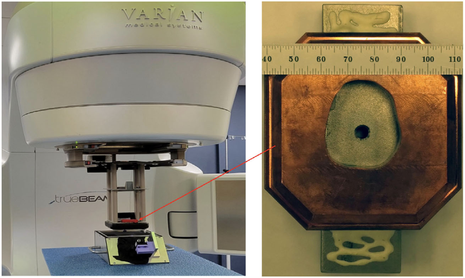
Methods: The FBSM uses a proprietary low mass, less than 0.5 mm water equivalent, non-hygroscopic, radiation tolerant scintillator material (designated HM: hybrid material) that is viewed by high frame rate CMOS cameras. Folded optics using mirrors enable a thin monitor profile of ∼10 cm. A field programmable gate array (FPGA) data acquisition system generates real-time analysis on a time scale appropriate to the FLASH RT beam modality: 100-1000 Hz for pulsed electrons and 10-20 kHz for quasi-continuous scanning proton pencil beams. An ion beam monitor served as the initial development platform for this work and was tested in low energy heavy-ion beams (86Kr+26 and protons). A prototype FBSM was fabricated and then tested in various radiation beams that included FLASH level dose per pulse electron beams, and a hospital RT clinic with electron beams.
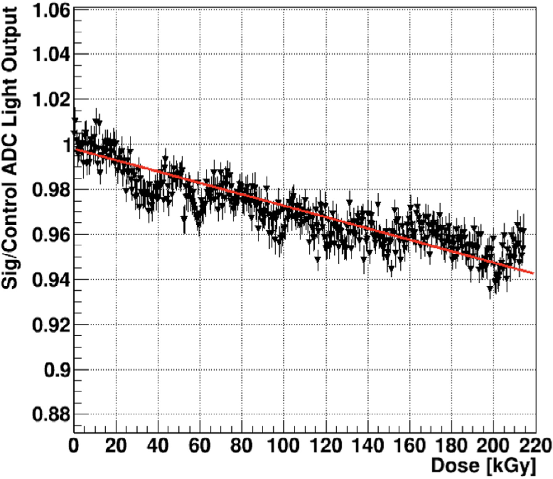
Results: Results presented in this report include image quality, response linearity, radiation hardness, spatial resolution, and real-time data processing. The HM scintillator was found to be highly radiation damage resistant. It exhibited a small 0.025%/kGy signal decrease from a 216 kGy cumulative dose resulting from continuous exposure for 15 min at a FLASH compatible dose rate of 237 Gy/s. Measurements of the signal amplitude versus beam fluence demonstrate linear response of the FBSM at FLASH compatible dose rates of >40 Gy/s. Comparison with commercial Gafchromic film indicates that the FBSM produces a high resolution 2D beam image and can reproduce a nearly identical beam profile, including primary beam tails. The spatial resolution was measured at 35-40 µm. Tests of the firmware beta version show successful operation at 20 000 Hz frame rate or 50 µs/frame, where the real-time analysis of the beam parameters is achieved in less than 1 µs.
Conclusions: The FBSM is designed to provide real-time beam profile monitoring over a large active area without significantly degrading the beam quality. A prototype device has been staged in particle beams at currents of single particles up to FLASH level dose rates, using both continuous ion beams and pulsed electron beams. Using a novel scintillator, beam profiling has been demonstrated for currents extending from single particles to 10 nA currents. Radiation damage is minimal and even under FLASH conditions would require ≥50 kGy of accumulated exposure in a single spot to result in a 1% decrease in signal output. Beam imaging is comparable to radiochromic films, and provides immediate images without hours of processing. Real-time data processing, taking less than 50 µs (combined data transfer and analysis times), has been implemented in firmware for 20 kHz frame rates for continuous proton beams.
Keywords: 2D beam imaging; FLASH Therapy; Radiation Therapy; fast real‐time beam monitor; radiation dosimetry.
© 2024 American Association of Physicists in Medicine.
Conflict of interest statement
CONFLICT OF INTEREST STATEMENT
Co-author Dr. Peter Friedman, President and CEO of Integrated Sensors, LLC, owns intellectual property rights to the innovations described in this paper.
Figures


Update of
-
A Prototype Scintillator Real-Time Beam Monitor for Ultra-high Dose Rate Radiotherapy.ArXiv [Preprint]. 2024 Mar 8:arXiv:2305.15306v3. ArXiv. 2024. Update in: Med Phys. 2024 Apr;51(4):2905-2923. doi: 10.1002/mp.17018. PMID: 37292473 Free PMC article. Updated. Preprint.
References
-
- Favaudon V, Caplier L, Monceau V, et al. Ultrahigh dose-rate FLASH irradiation increases the differential response between normal and tumor tissue in mice. Sci Transl Med 2014;6(245):24. - PubMed
