

Does the index in Morse taper connection affect the abutment stability? An in vitro experimental study
- PMID: 38457413
- PMCID: PMC10923422
- DOI: 10.1371/journal.pone.0298462
Does the index in Morse taper connection affect the abutment stability? An in vitro experimental study
Abstract
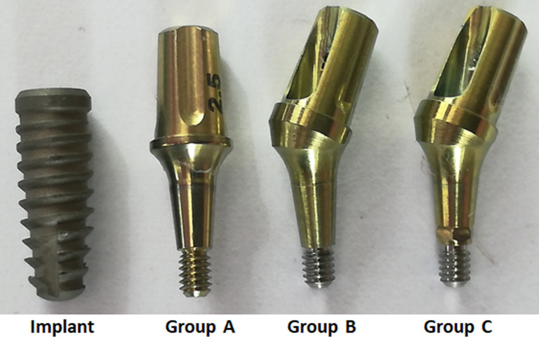
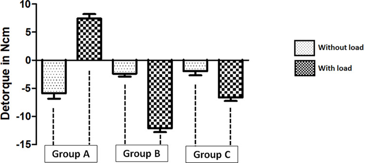
The present study compared three different implant and abutment sets of type Morse taper (MT) connection, with- and without-index, were analyzed regarding their mechanical behavior without and with cyclic load application simulating the masticatory function. Ninety implant and abutment (IA) sets were used in the present study, divided into three groups (n = 30 samples per group): Group A, Ideale solid straight abutment (one piece) without index; Group B, Ideale abutment with an angle of 30-degree (two pieces) without index; Group C, Ideale abutment with an angle of 30-degree (two pieces) with index. The abutment stability quotient (ASQ) values, detorque value and rotation angle were measured before and after the cycling load. Twenty IA sets of each group were submitted to mechanical load at 360,000 cycles. The ASQ without load were 64.7 ± 2.49 for the group A, 60.2 ± 2.64 for the group B, 54.4 ± 3.27 for the group C; With load were 66.1 ± 5.20 for the group A, 58.5 ± 6.14 for the group B, 58.9 ± 2.99 for the group C. Detorque values were lower in groups B and C compared to group A (p < 0.05). In conclusion, the presence of the index did not influence the stability values. However, solid straight abutments (group A) showed higher values of stability compared to groups of angled abutments (groups B and C).
Copyright: © 2024 Goyeneche et al. This is an open access article distributed under the terms of the Creative Commons Attribution License, which permits unrestricted use, distribution, and reproduction in any medium, provided the original author and source are credited.
Conflict of interest statement
The authors have declared that no competing interests exist.
Figures


Similar articles
-
Mechanical Behavior of Five Different Morse Taper Implants and Abutments with Different Conical Internal Connections and Angles: An In Vitro Experimental Study.J Funct Biomater. 2024 Jun 28;15(7):177. doi: 10.3390/jfb15070177. J Funct Biomater. 2024. PMID: 39057299 Free PMC article.
-
Effect of internal hexagonal index on removal torque and tensile removal force of different Morse taper connection abutments.J Prosthet Dent. 2017 May;117(5):621-627. doi: 10.1016/j.prosdent.2016.07.024. Epub 2016 Oct 27. J Prosthet Dent. 2017. PMID: 27881313
-
Behavior of implant and abutment sets of three different connections during the non-axial load application: An in vitro experimental study using a radiographic method.Biomed Mater Eng. 2022;33(2):101-112. doi: 10.3233/BME-211221. Biomed Mater Eng. 2022. PMID: 34511480
-
A new design of a multifunctional abutment to morse taper implant connection: Experimental mechanical analysis.J Mech Behav Biomed Mater. 2021 Apr;116:104347. doi: 10.1016/j.jmbbm.2021.104347. Epub 2021 Jan 22. J Mech Behav Biomed Mater. 2021. PMID: 33513461
-
Morse taper dental implants and platform switching: The new paradigm in oral implantology.Eur J Dent. 2016 Jan-Mar;10(1):148-154. doi: 10.4103/1305-7456.175677. Eur J Dent. 2016. PMID: 27011755 Free PMC article. Review.
Cited by
-
Evaluating the microgap and sealing capability in four implant systems with different interlockings under different tightening torques: an in-vitro study.J Adv Prosthodont. 2024 Dec;16(6):336-347. doi: 10.4047/jap.2024.16.6.336. Epub 2024 Dec 19. J Adv Prosthodont. 2024. PMID: 39803384 Free PMC article.
-
Mechanical Behavior of Five Different Morse Taper Implants and Abutments with Different Conical Internal Connections and Angles: An In Vitro Experimental Study.J Funct Biomater. 2024 Jun 28;15(7):177. doi: 10.3390/jfb15070177. J Funct Biomater. 2024. PMID: 39057299 Free PMC article.
References
-
- Choi S, Kang YS, Yeo I-SL. Influence of Implant–Abutment Connection Biomechanics on Biological Response: A Literature Review on Interfaces between Implants and Abutments of Titanium and Zirconia. Prosthesis. 2023; 5(2):527–538.
-
- Da Silva JM, Sobral BS, Cabral CT, Souza CMS, Fonseca RRS, Ramacciato JC. Evaluation of tensile strength after insertions and removals of abutments on frictional Morse taper implants. Int J Odontostomatol. 2021;15(2):356–362.
LinkOut - more resources
Full Text Sources
