. 2024 Mar 9;14(1):5815.
doi: 10.1038/s41598-024-55204-4.

Voltage-controlled two-dimensional Fresnel diffraction pattern in quantum dot molecules

Affiliations

Voltage-controlled two-dimensional Fresnel diffraction pattern in quantum dot molecules

Hamed Mehrabzadeh et al. Sci Rep. .

Abstract

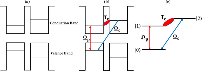
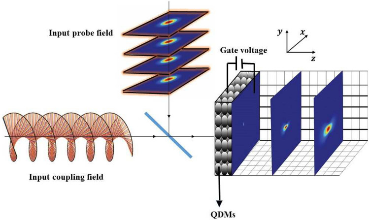
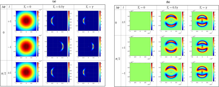
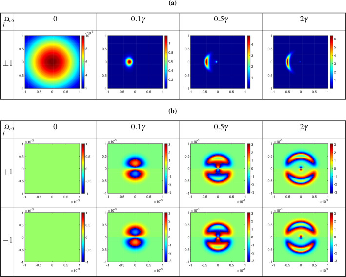
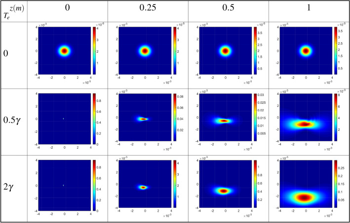
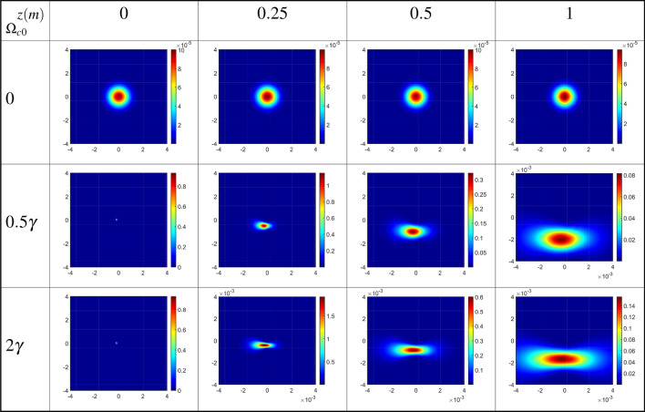
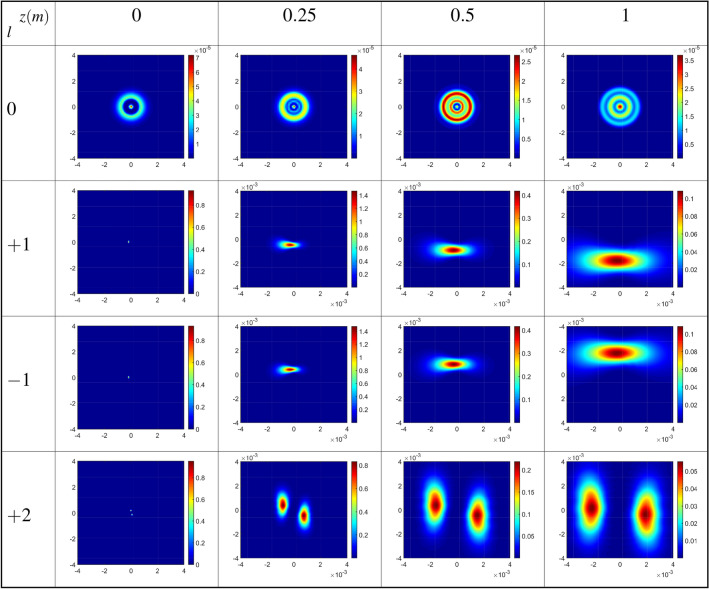
This study explores the influence of inter-dot tunneling effects within a quantum dot molecule on the Fresnel diffraction phenomenon. Our findings indicate that the Fresnel diffraction of the output probe Gaussian field can be manipulated by adjusting the inter-dot tunneling parameter's strength and the characteristics of the coupling field. The inter-dot tunneling effect establishes a closed-loop system, setting conditions for the interference of the applied fields. We specifically examine a Laguerre-Gaussian (LG) coupling field, investigating how its properties-such as strength, value, and sign of the orbital angular momentum (OAM)-impact the Fresnel diffraction of the output probe field. Increasing the inter-dot tunneling parameter and the coupling LG field's strength allows for control over the spatial distribution of the Fresnel diffraction pattern. Notably, the inter-dot tunneling parameter can disturb the symmetry of the diffraction patterns. Additionally, considering a negative OAM for the coupling LG field transforms the diffraction pattern into its inverse shape. This suggests that, in the presence of the inter-dot tunneling effect, the Fresnel diffraction pattern is contingent on the direction of rotation of the helical phase front of the coupling LG field. Our results offer insights into quantum control of Fresnel diffraction patterns and the identification of OAM in LG beams, presenting potential applications in quantum technologies.


Conflict of interest statement

The authors declare no competing interests.

Figures

Figure 1
Figure 1
Band diagram of a QDM interacting with probe and coupling fields (a) before and (b) after applying the gate voltage. (c) Schematic diagram of the energy levels QDM system.
Figure 2
Figure 2
A general schematics of the introduced QDM system interacting with two applied fields and the intensity profiles of the diffracted output probe field.
Figure 3
Figure 3
Output probe amplitude (a), and phase (b) profiles at the exit plane of the medium, Z=L, as a function of x and y for different values of the tunneling parameter and two opposite modes of the coupling LG field, i.e. l=1 and -1. The horizontal, x, and vertical, y, axes are taken in mm. Used parameters related to the QDM system are considered to be Γ20=γ20=0, γ10=0.554γ, Γ10=5.54γ, Γ12=2γ, γ=1meV, and α=10. The applied fields characteristics are chosen to be wG=1.1mm, Ωp0=0.1γ, Ep0=0.01, wLG=270 μm, and Ωc0=γ, under two-photon resonance condition Δp=Δc=0.
Figure 4
Figure 4
Output probe amplitude (a) and phase (b) profiles at the exit plane of the medium versus x and y for different values of the constant Rabi frequency of coupling LG field and Te=γ under the same parameters of Fig. 3.
Figure 5
Figure 5
Diffraction patterns of the output probe field as a function of x and y in the absence (Te=0), first row, and in the presence of the inter-dot tunneling effect (Te=0.5γ), second row, and (Te=2γ), third row, for positive (l=1) OAM values of the coupling LG field at different distances from the exit plane of the QDM medium. The wavelength of the probe field is fixed at λp=870nm. Other parameters are the same as in Fig. 3.
Figure 6
Figure 6
Diffraction patterns of the output probe field as a function of x and y for different values of the constant Rabi frequency of coupling LG field, as the first LG mode l=1, and Te=γ at different distances from the exit plane of the QDM medium. Other used parameters are the same as in Fig. 5.
Figure 7
Figure 7
Diffraction patterns of the output probe field versus x and y for different OAM values of the coupling LG field at different distances from the exit plane of the QDM medium. The value of tunneling parameter is considered to be Te=γ under the same parameters of Fig. 5.

Similar articles

References

    1. Talbot HF. Facts relating to optical science. Philos. Mag. 1836;9:401–407.
    1. Alkaisi MM, Blaikie RJ, McNab SJ, Cheung R, Cumming DRS. Sub-diffraction-limited patterning using evanescent near-field optical lithography. Appl. Phys. Lett. 1999;75:3560–3562. doi: 10.1063/1.125388. - DOI
    1. Naqavi A, Peter Herzig H, Rossi M. High-contrast self-imaging with ordered optical elements. J. Opt. Soc. Am. B. 2016;33:2374–2382. doi: 10.1364/JOSAB.33.002374. - DOI
    1. Rasouli S, Hebri D. Contrast-enhanced quarter-Talbot images. J. Opt. Soc. Am. A. 2017;34:2145–2156. doi: 10.1364/JOSAA.34.002145. - DOI - PubMed
    1. Rasouli S, Hebri D. Theory of diffraction of vortex beams from 2D orthogonal periodic structures and Talbot self-healing under vortex beam illumination. J. Opt. Soc. Am. A. 2019;36:800–808. doi: 10.1364/JOSAA.36.000800. - DOI - PubMed