[Preprint]. 2024 Mar 2:2024.03.01.582964.
doi: 10.1101/2024.03.01.582964.

Phosphatidic acid is an endogenous negative regulator of PIEZO2 channels and mechanical sensitivity

Affiliations

Phosphatidic acid is an endogenous negative regulator of PIEZO2 channels and mechanical sensitivity

Matthew Gabrielle et al. bioRxiv. .

Update in

Abstract

Mechanosensitive PIEZO2 ion channels play roles in touch, proprioception, and inflammatory pain. Currently, there are no small molecule inhibitors that selectively inhibit PIEZO2 over PIEZO1. The TMEM120A protein was shown to inhibit PIEZO2 while leaving PIEZO1 unaffected. Here we find that TMEM120A expression elevates cellular levels of phosphatidic acid and lysophosphatidic acid (LPA), aligning with its structural resemblance to lipid-modifying enzymes. Intracellular application of phosphatidic acid or LPA inhibited PIEZO2, but not PIEZO1 activity. Extended extracellular exposure to the non-hydrolyzable phosphatidic acid and LPA analogue carbocyclic phosphatidic acid (ccPA) also inhibited PIEZO2. Optogenetic activation of phospholipase D (PLD), a signaling enzyme that generates phosphatidic acid, inhibited PIEZO2, but not PIEZO1. Conversely, inhibiting PLD led to increased PIEZO2 activity and increased mechanical sensitivity in mice in behavioral experiments. These findings unveil lipid regulators that selectively target PIEZO2 over PIEZO1, and identify the PLD pathway as a regulator of PIEZO2 activity.


Conflict of interest statement

DECLARATION OF INTERESTS The authors declare no competing interests.

Figures
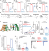
Figure 1.
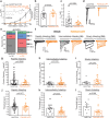
Figure 1.. Changes in cellular lipid content mediate inhibition of PIEZO2 by TMEM120A
(a) LC-MS/MS experiments using N2A-Pz1-KO cells transiently transfected with vector (mock, black), TMEM120A (red), or TMEM120B (blue) as described in the methods section. Scatter plots and mean ± SEM of the relative saturated lipid intensities detected for n=3 independent transfections for LPA (ANOVA, F(2,6)=9.274, p=0.0146), phosphatidic acid (PA) (ANOVA, F(2,6)=1148, p 1.77×10⁻⁸), DG (ANOVA, F(2,6)=5.528, p=0.0435), TG (ANOVA, F(2,6)=44.500, p=0.0002). P values for post-hoc Tukey tests are displayed on plots. (b) Scheme of the Kennedy pathway for de novo TG synthesis. Lipids are depicted with short acyl chains because of spatial restrictions. (c) Structure of TMEM120A with magnified (black box) of residues interacting with CoA generated using PyMOL from the publicly available pdb file 7F3T. (d) Whole-cell voltage clamp experiments at −60 mV in N2A-Pz1-KO cells transiently transfected with PIEZO2-GFP, and tdTOMATO (black), TMEM120A-tdTom-WT (red), or TMEM120A-tdTom-W193A (blue). Mechanically-activated currents were evoked by indentations of increasing depth with a blunt glass probe. Current amplitudes are plotted (mean ± SEM) and statistical difference for the area under curve (AUC) for 4.0–8.0 µm stimuli calculated with the Mann-Whitney test. (e) Scatter and mean ± SEM for the threshold of membrane indentation to elicit mechanically-activated current (Mann-Whitney). (f) Percent of cells displaying mechanically-activated currents. (g) Scatter and mean ± SEM for maximum currents (Kruskal-Wallis, χ2=17.467, df=2, p=0.0001; Mann-Whitney tests displayed). (h) Representative current traces.
Figure 2.
Figure 2.. Phosphatidic acid inhibits PIEZO2 but not PIEZO1.
Whole-cell patch-clamp experiments at −60 mV in N2A-Pz1-KO cells transiently transfected with PIEZO2-GFP or PIEZO1-GFP with patch-pipette solution supplemented with the indicated lipids as described in the methods section. (a-d) PIEZO2-GFP transfected cells supplemented with 300 μM dioctanoyl-phosphatidic acid (PA). (a) Current amplitudes are plotted (mean ± SEM) and statistical difference for the area under curve (AUC) for 4.0–8.0 µm stimuli calculated with the Mann-Whitney test. (b) Membrane indentation depth threshold to elicit mechanically-activated current (t-test). (c) Maximum current amplitudes (Mann-Whitney). (d) Representative current traces. (e-h) PIEZO1-GFP transfected cells supplemented with 300 μM dioctanoyl-phosphatidic acid. (e) Current amplitudes are plotted (mean ± SEM) and statistical difference of AUC for 4.0–8.0 µm stimuli calculated with the Mann-Whitney test. (f) Membrane indentation depth threshold to elicit mechanically-activated current (Mann-Whitney). (g) Maximum current amplitudes (Mann-Whitney). (h) Representative current traces. All bar graphs plotted with scatter and mean ± SEM.
Figure 3.
Figure 3.. LPA inhibits PIEZO2 but not PIEZO1
Whole-cell patch-clamp experiments at −60 mV in N2A-Pz1-KO cells transiently transfected with PIEZO2-GFP or PIEZO1-GFP with patch-pipette solution supplemented with the indicated lipids as described in the methods section. (a-d) PIEZO2-GFP expressing cells supplemented with 30 μM palmitoyl-LPA. (a) Current amplitudes are plotted (mean ± SEM) and statistical difference of AUC for 4.0–8.0 µm stimuli calculated with the Mann-Whitney test. (b) Membrane indentation depth threshold to elicit mechanically-activated currents (Mann-Whitney). (c) Maximum current amplitudes (Mann-Whitney). (d) Representative current traces. (e-h) PIEZO1-GFP expressing cells supplemented with 30 μM palmitoyl-LPA. (e) Current amplitudes are plotted (mean ± SEM) and statistical difference of AUC for 4.0–8.0 µm stimuli calculated with the Mann-Whitney test. (f) Membrane indentation depth threshold to elicit mechanically-activated current (Mann-Whitney). (g) Maximum current amplitudes (Mann-Whitney). (h) Representative current traces. All bar graphs plotted with scatter and mean ± SEM.
Figure 4.
Figure 4.. Extracellular application of ccPA inhibits PIEZO2 currents.
Whole-cell patch-clamp experiments performed at −60 mV as described in the methods section. (a-d) N2A-Pz1-KO cells transiently transfected with PIEZO2-GFP mock treated (black) or treated with extracellular palmitoyl-ccPA overnight (orange). (a) Current amplitudes are plotted (mean ± SEM) and statistical difference the area under curve (AUC) for 4.0–8.0 µm stimuli calculated with the Mann-Whitney test. (b) Membrane indentation depth threshold to elicit mechanically-activated currents (t-test). (c) Maximum current amplitudes (Mann-Whitney). (d) Representative current traces. (e-l). Isolated mouse DRG neurons mock treated (black) or treated with extracellular palmitoyl-ccPA overnight (orange). (e) Proportion of rapidly adapting (RA), intermediately adapting (IA), slowly adapting (SA) and non-responders (NR). Chi-squared test. (f) Representative current traces. (g) Rapidly adapting maximum current density (t-test). (h) Intermediate adapting maximum current density (t-test). (i) Slowly adapting maximum current density (Mann-Whitney). (j) Membrane indentation depth threshold to elicit rapidly adapting current (t-test). (k) Membrane indentation depth threshold to elicit intermediately adapting current (t-test). (l) Membrane indentation depth threshold to elicit slowly adapting current (Mann-Whitney). All bar graphs plotted with scatter and mean ± SEM.
Figure 5.
Figure 5.. Optogenetic activation of PLD inhibits PIEZO2.
Whole-cell patch-clamp experiments at −60 mV in N2A-Pz1-KO cells transfected with PIEZO2-GFP and active Opto-PLD (black) or inactive Opto-PLD (orange; H170A) as described in the methods section. (a) Scheme of blue light activation of the Opto-PLD system (generated with BioRender) with representative images for mCherry fluorescence (60x) before and after blue light exposure. (b) PIEZO2-GFP currents with fixed, continuous membrane indentations after blue light exposure normalized to currents before blue light. (c) Representative current traces. Blue shaded area indicates blue light exposure. - Downward deflections indicate mechanically-activate Piezo2 currents (d) Scatter and mean ± SEM for PIEZO2-GFP co-expressed with inactive Opto-PLD after blue light exposure (Repeated-Measures ANOVA, F=0.365, df=2,10, p=0.702; paired t-tests displayed). (e) Scatter and mean ± SEM for PIEZO2-GFP co-expressed with active Opto-PLD after blue light exposure (Repeated-Measures ANOVA, F=21.386, df=2,14, p=5.546×10⁻⁵; paired t-tests displayed). (f) Scatter and mean ± SEM of PIEZO2-GFP with inactive or active Opto-PLD after 9.5 min of blue light exposure (t-test).
Figure 6.
Figure 6.. Phospholipase D (PLD) negatively regulates PIEZO2 but not PIEZO1.
Whole-cell patch-clamp experiments at −60 mV in transiently transfected N2A-Pz1-KO cells as described in the methods section. (a) Scheme of PLD inhibition by FIPI. (b-e) N2A-Pz1-KO cells transiently transfected with PIEZO2-GFP and were treated with DMSO (black) or 500 nM FIPI (orange) for 30 min, see methods for details. (b) Current amplitudes are plotted (mean ± SEM) and statistical difference of AUC for 4.0–8.0 µm stimuli calculated with the Mann-Whitney test. (d) Membrane indentation depth threshold to elicit mechanically-activated current (Mann-Whitney). (d) Maximum current amplitudes (Mann-Whitney). (e) Representative current traces. (f-i) N2A-Pz1-KO cells transiently transfected with PIEZO1-GFP treated with 500 nM FIPI (orange) for 30 min or the vehicle DMSO (blue). (f) Current amplitudes are plotted (mean ± SEM) and statistical difference of AUC for 4.0–8.0 µm stimuli calculated with the Mann-Whitney test. (g) Membrane indentation depth threshold to elicit mechanically-activated currents (Mann-Whitney). (h) Maximum current amplitudes (Mann-Whitney). (i) Representative current traces. (j-m) N2A-Pz1-KO cells transiently transfected with PIEZO2-GFP alone (black), or together with PLD1 (blue), or PLD2 (orange). (j) Current amplitudes are plotted (mean ± SEM) and statistical difference of AUC for 4.0–8.0 µm stimuli calculated was with the Mann-Whitney test. (k) Membrane indentation depth threshold to elicit mechanically-activated current (Kruskal-Wallis, χ2=3.298, df=2, p=0.0192; Mann-Whitney tests displayed). (l) Maximum current amplitudes (Kruskal-Wallis, χ2=7,906, df=2, p=0.0192; Mann-Whitney tests displayed). (m) Representative current traces. All bar graphs plotted with scatter and mean ± SEM.
Figure 7.
Figure 7.. PLD modulates native rapidly adapting mechanically-activated currents in peripheral sensory neurons.
(a-d) Whole-cell patch-clamp at −60 mV in hiPSC-sensory neurons treated with 500 nM FIPI (orange) or DMSO (black) as described in the methods section for details. (a) Current densities are plotted (mean ± SEM) and statistical difference of AUC for 4.0–8.0 µm stimuli calculated with the Mann-Whitney test. (b) Membrane indentation depth thresholds to elicit mechanically-activated current (Mann-Whitney). (c) Maximum current densities (Mann-Whitney). (d) Representative current traces. (e) Whole-cell patch-clamp at −60 mV in isolated mouse DRG neurons treated with DMSO (black) or FIPI (orange) as described in the methods section. Representative current traces (top), and membrane indentation depth thresholds to elicit mechanically-activated RA currents (bottom) (t-test). (f-g) Whole-cell current-clamp in isolated mouse DRG neurons treated with DMSO (black) or FIPI (orange) as described in the methods section. (f) Representative traces (top), and membrane indentation depth threshold to elicit an action potential (bottom) (t-test). (g) Representative traces (top), and current injection threshold to elicit an action potential (bottom) (t-test) in the same cells used in panels E and F. In three cells the seal was lost before current injections could be performed All bar graphs plotted with scatter and mean ± SEM. (h-j) Mechanical testing using Von Frey filaments and thermal testing using the Hargreaves apparatus were performed on mice receiving an I.P. injection of FIPI (n=14) or vehicle (n=14) as described in the methods section. (h) Experimental design (generated with BioRender). (i) von Frey testing 50% mechanical threshold (Mann-Whitney). (j) Hargreaves paw withdrawal latency (Mann-Whitney).

References

    1. Coste B., Mathur J., Schmidt M., Earley T.J., Ranade S., Petrus M.J., Dubin A.E., and Patapoutian A. (2010). Piezo1 and Piezo2 are essential components of distinct mechanically activated cation channels. Science 330, 55–60. 10.1126/science.1193270. - DOI - PMC - PubMed
    1. Szczot M., Nickolls A.R., Lam R.M., and Chesler A.T. (2021). The Form and Function of PIEZO2. Annu Rev Biochem 90, 507–534. 10.1146/annurev-biochem-081720-023244. - DOI - PMC - PubMed
    1. Murthy S.E., Dubin A.E., and Patapoutian A. (2017). Piezos thrive under pressure: mechanically activated ion channels in health and disease. Nat Rev Mol Cell Biol 18, 771–783. 10.1038/nrm.2017.92. - DOI - PubMed
    1. Xiao B. (2020). Levering Mechanically Activated Piezo Channels for Potential Pharmacological Intervention. Annu Rev Pharmacol Toxicol 60, 195–218. 10.1146/annurev-pharmtox-010919-023703. - DOI - PubMed
    1. Syeda R., Xu J., Dubin A.E., Coste B., Mathur J., Huynh T., Matzen J., Lao J., Tully D.C., Engels I.H., et al. (2015). Chemical activation of the mechanotransduction channel Piezo1. Elife 4. 10.7554/eLife.07369. - DOI - PMC - PubMed

Publication types