. 2024 Mar 11;15(1):2172.
doi: 10.1038/s41467-024-46502-6.

Float-stacked graphene-PMMA laminate

Affiliations

Float-stacked graphene-PMMA laminate

Seung-Il Kim et al. Nat Commun. .

Abstract

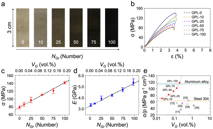
Semi-infinite single-atom-thick graphene is an ideal reinforcing material that can simultaneously improve the mechanical, electrical, and thermal properties of matrix. Here, we present a float-stacking strategy to accurately align the monolayer graphene reinforcement in polymer matrix. We float graphene-poly(methylmethacrylate) (PMMA) membrane (GPM) at the water-air interface, and wind-up layer-by-layer by roller. During the stacking process, the inherent water meniscus continuously induces web tension of the GPM, suppressing wrinkle and folding generation. Moreover, rolling-up and hot-rolling mill process above the glass transition temperature of PMMA induces conformal contact between each layer. This allows for pre-tension of the composite, maximizing its reinforcing efficiency. The number and spacing of the embedded graphene fillers are precisely controlled. Notably, we accurately align 100 layers of monolayer graphene in a PMMA matrix with the same intervals to achieve a specific strength of about 118.5 MPa g-1 cm3, which is higher than that of lightweight Al alloy, and a thermal conductivity of about 4.00 W m-1 K-1, which is increased by about 2,000 %, compared to the PMMA film.


Conflict of interest statement

The authors declare no competing interests.

Figures

Fig. 1
Fig. 1. Manufacture of the graphene-PMMA laminate (GPL) via float-stacking process.
a Schematic of the float-stacking process of the GPL. (i) Floating the graphene–PMMA membrane (GPM) on DI water bath after wet-etching of the bottom Cu foil, (ii) Layer-by-layer stacking of GPMs by rolling process, (iii) Cutting and unfolding of stacked-GPM, and (iv) Hot-rolling mill process of the stacked-GPM. b Photograph of the as-prepared GPL with 100 layers of GPM (GPL − 100). c, d Cross-sectional SEM and TEM images of the GPL − 100. Monolayer graphene is placed between the PMMA matrix without structure defects. Scale bar: 100 μm and 5 nm, respectively.
Fig. 2
Fig. 2. Mechanical characterization of the graphene-PMMA laminates (GPLs).
a Photograph of the GPLs with different numbers of graphene reinforcement layers of (0, 10, 25, 50, 75, and 100). b Typical stress–strain responses of GPLs. c, d Fracture strength, and Young’s modulus of the GPLs. Both mechanical properties of GPLs linearly increased according to the number (or the volume fraction) of embedded graphene layers. The error bars represent the standard deviations (n=3). e Comparison of the specific strength of GPLs with that of the previously reported graphene/PMMA composites. Source data are provided as a Source Data file.
Fig. 3
Fig. 3. Reinforcing mechanism of the graphene-PMMA laminate (GPL).
a Tensile curve and b, c SEM images of the simply-stacked GPL (S–GPL), stacked above the Tg (Tg–GPL), and GPL, respectively. Scale bar: 50 μm and 1 μm, respectively. d Raman spectra of the corresponding GPLs under 532 nm excitation. Both the G and 2D peak positions are gradually red-shifted with the heat-treatment step. eg G peak position vs. 2D peak position of three different GPLs: e S–GPL, f Tg–GPL, and g GPL. Source data are provided as a Source Data file.
Fig. 4
Fig. 4. Thermal properties of the graphene-PMMA laminates (GPLs).
a Time-dependent IR image from GPL − 0 to GPL − 100. Scale bar: 1 mm. b Temperature difference from GPL − 0 to GPL − 100 according to the distance measured from the IR images. The temperature of GPL − 100 was higher than that of GPL − 0 in all sections of the composite. c Comparison of thermal conductivity with GPL and various graphene/PMMA composites from the literature against the graphene volume fraction. The blue dashed line calculated through the graphene thermal conductivity (K = (400 to 2500) W m−1 K−1) limits the range of parallel orientation, and the random orientation area calculated by the Maxwell–Eucken (ME) model covers various reported graphene/PMMA composites. d In-plane thermal simulation of the bare PMMA (GPL − 0) and graphene/PMMA (GPL − 100) composite, with different heat conduction times (t = (0 to 1) μs). Scale bar: 1 μm. Source data are provided as a Source Data file.

References

    1. Liu Y, et al. Promises and prospects of two-dimensional transistors. Nature. 2021;591:43–53. doi: 10.1038/s41586-021-03339-z. - DOI - PubMed
    1. Xin N, et al. Concepts in the design and engineering of single-molecule electronic devices. Nat. Rev. Phys. 2019;1:211–230. doi: 10.1038/s42254-019-0022-x. - DOI
    1. Del Alamo JA. Nanometre-scale electronics with III–V compound semiconductors. Nature. 2011;479:317–323. doi: 10.1038/nature10677. - DOI - PubMed
    1. Xu X, Chen J, Zhou J, Li B. Thermal conductivity of polymers and their nanocomposites. Adv. Mater. 2018;30:1705544. doi: 10.1002/adma.201705544. - DOI - PubMed
    1. Ding S-C, et al. High thermal conductivity and remarkable damping composite gels as thermal interface materials for heat dissipation of chip. Chip. 2022;1:100013. doi: 10.1016/j.chip.2022.100013. - DOI