

Histology-validated electromagnetic characterization of ex-vivo ovine lung tissue for microwave-based medical applications
- PMID: 38467672
- PMCID: PMC10928158
- DOI: 10.1038/s41598-024-55035-3
Histology-validated electromagnetic characterization of ex-vivo ovine lung tissue for microwave-based medical applications
Abstract
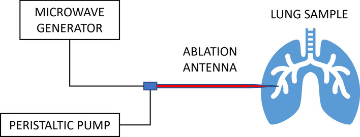
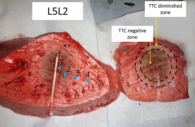
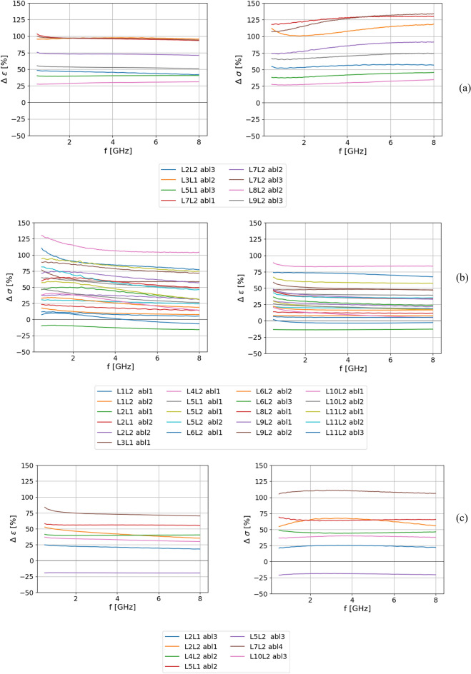
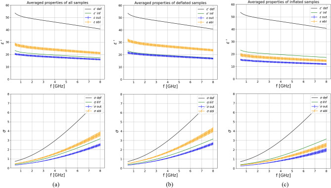
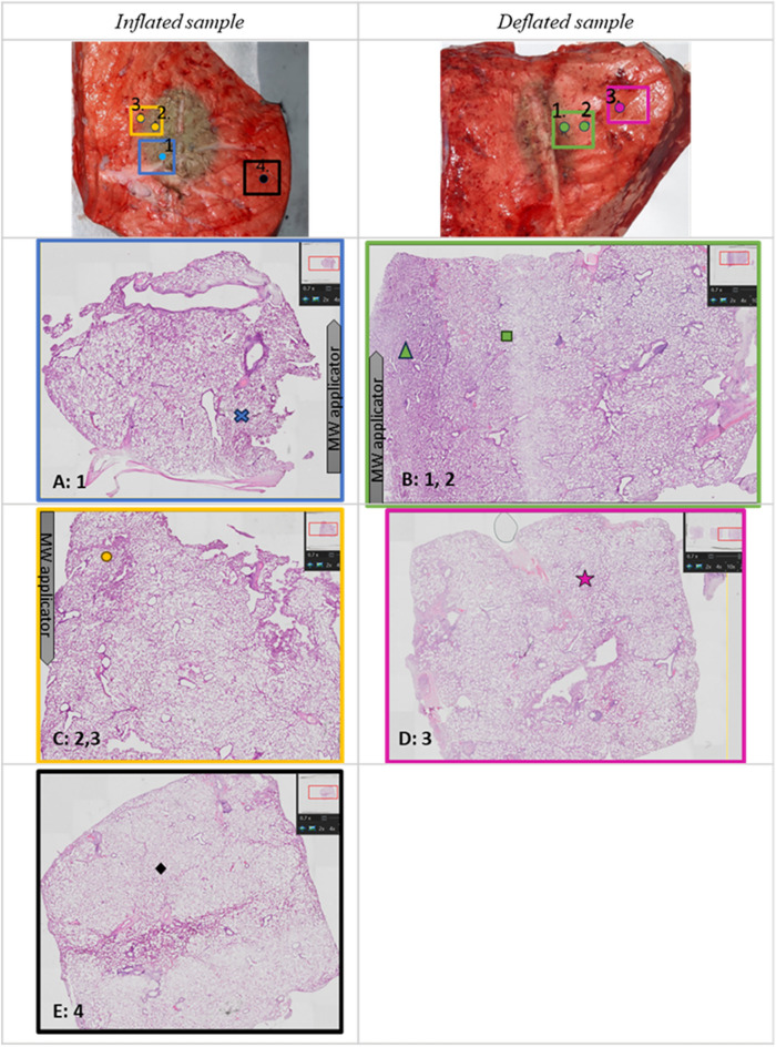
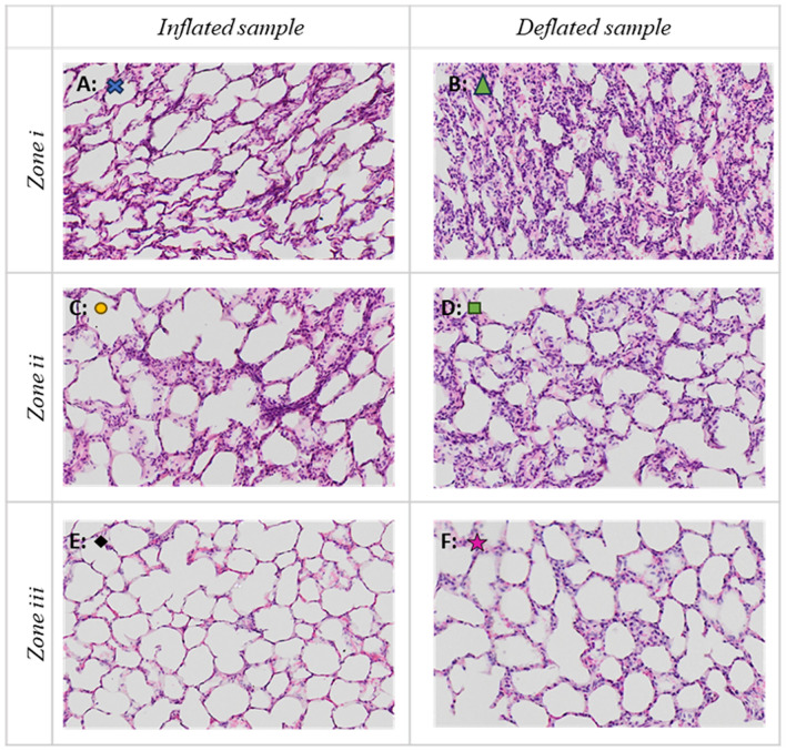
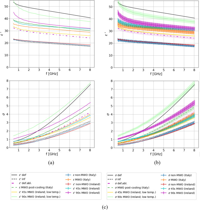
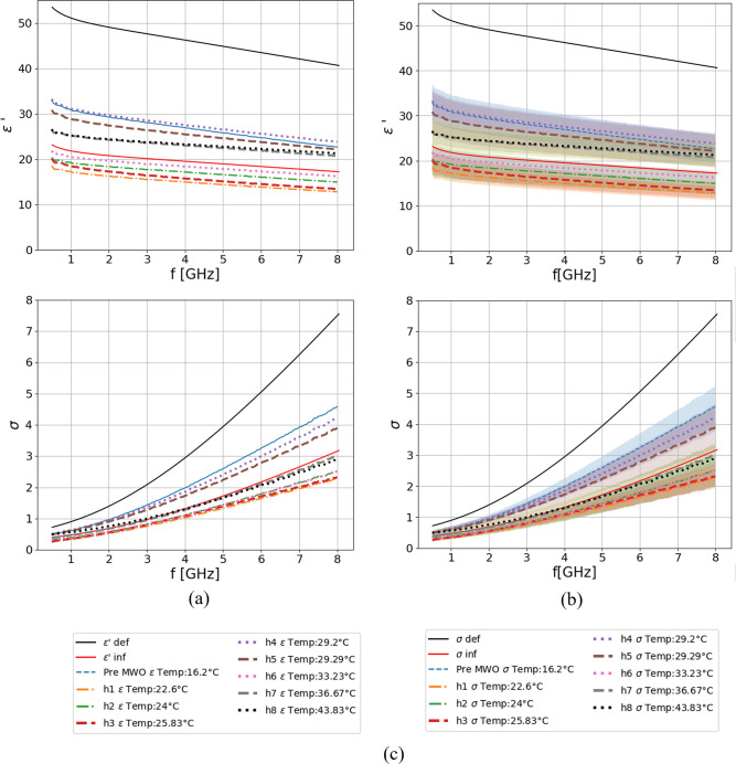
Microwave thermal ablation is an established therapeutic technique for treating malignant tissue in various organs. Its success greatly depends on the knowledge of dielectric properties of the targeted tissue and on how they change during the treatment. Innovation in lung navigation has recently increased the clinical interest in the transbronchial microwave ablation treatment of lung cancer. However, lung tissue is not largely characterized, thus its dielectric properties investigation prior and post ablation is key. In this work, dielectric properties of ex-vivo ovine lung parenchyma untreated and ablated at 2.45 GHz were recorded in the 0.5-8 GHz frequency range. The measured dielectric properties were fitted to 2-pole Cole-Cole relaxation model and the obtained model parameters were compared. Based on observed changes in the model parameters, the physical changes of the tissue post-ablation were discussed and validated through histology analysis. Additionally, to investigate the link of achieved results with the rate of heating, another two sets of samples, originating from both ovine and porcine tissues, were heated with a microwave oven for different times and at different powers. Dielectric properties were measured in the same frequency range. It was found that lung tissue experiences a different behavior according to heating rates: its dielectric properties increase post-ablation while a decrease is found for low rates of heating. It is hypothesized, and validated by histology, that during ablation, although the tissue is losing water, the air cavities deform, lowering air content and increasing the resulting tissue properties.
© 2024. The Author(s).
Conflict of interest statement
The authors declare no competing interests.
Figures
Similar articles
-
Changes in the dielectric properties of ex vivo bovine liver during microwave thermal ablation at 2.45 GHz.Phys Med Biol. 2012 Apr 21;57(8):2309-27. doi: 10.1088/0031-9155/57/8/2309. Epub 2012 Mar 30. Phys Med Biol. 2012. PMID: 22460062
-
Exploiting Tissue Dielectric Properties to Shape Microwave Thermal Ablation Zones.Sensors (Basel). 2020 Jul 16;20(14):3960. doi: 10.3390/s20143960. Sensors (Basel). 2020. PMID: 32708680 Free PMC article.
-
Broadband lung dielectric properties over the ablative temperature range: Experimental measurements and parametric models.Med Phys. 2019 Oct;46(10):4291-4303. doi: 10.1002/mp.13704. Epub 2019 Aug 10. Med Phys. 2019. PMID: 31286530 Free PMC article.
-
Treatment planning in microwave thermal ablation: clinical gaps and recent research advances.Int J Hyperthermia. 2017 Feb;33(1):83-100. doi: 10.1080/02656736.2016.1214883. Epub 2016 Aug 21. Int J Hyperthermia. 2017. PMID: 27431328 Review.
-
Review of temperature dependence of thermal properties, dielectric properties, and perfusion of biological tissues at hyperthermic and ablation temperatures.Crit Rev Biomed Eng. 2014;42(6):467-92. doi: 10.1615/critrevbiomedeng.2015012486. Crit Rev Biomed Eng. 2014. PMID: 25955712 Free PMC article. Review.
References
-
- Wang M, Crocco L, Cavagnaro M. On the design of a microwave imaging system to monitor thermal ablation of liver tumors. IEEE J. Electromagn. RF Microw. Med. Biol. 2021;5:231–237. doi: 10.1109/JERM.2020.3048846. - DOI
-
- Babarinde, O. J., Jamlos, M. F., Soh, P. J., Schreurs, D. M. M.-P. & Beyer, A. Microwave imaging technique for lung tumour detection. In 2016 German Microwave Conference (GeMiC). 100–103 10.1109/GEMIC.2016.7461566 (IEEE, 2016).
-
- Farina, L., Ruvio, G. & O’Halloran, M. Lung tumor mimicking models for usability validation of transbronchial microwave thermal ablation procedures. In 2021 IEEE International Conference on Microwaves, Antennas, Communications and Electronic Systems (COMCAS). 135–139 10.1109/COMCAS52219.2021.9628998 (IEEE, 2021).
MeSH terms
Grants and funding
LinkOut - more resources
Full Text Sources
