

Finite Element Analysis and Fatigue Test of INTEGRA Dental Implant System
- PMID: 38473684
- PMCID: PMC10934518
- DOI: 10.3390/ma17051213
Finite Element Analysis and Fatigue Test of INTEGRA Dental Implant System
Abstract
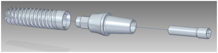
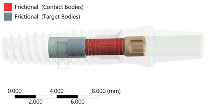
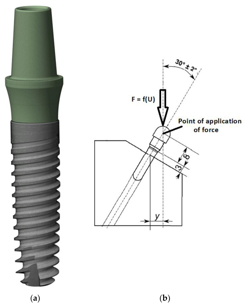
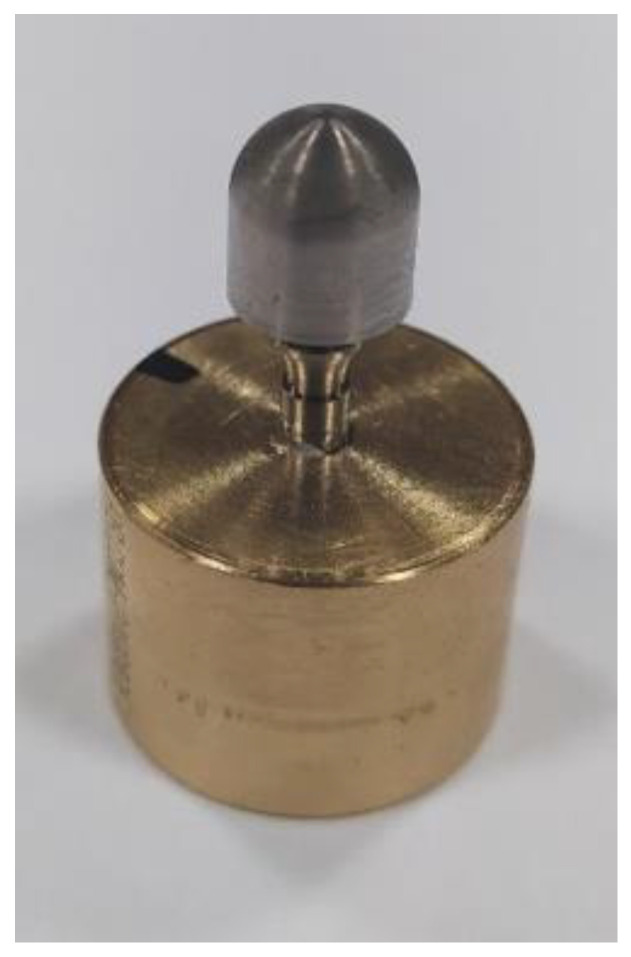
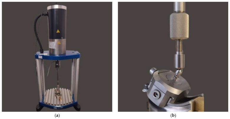
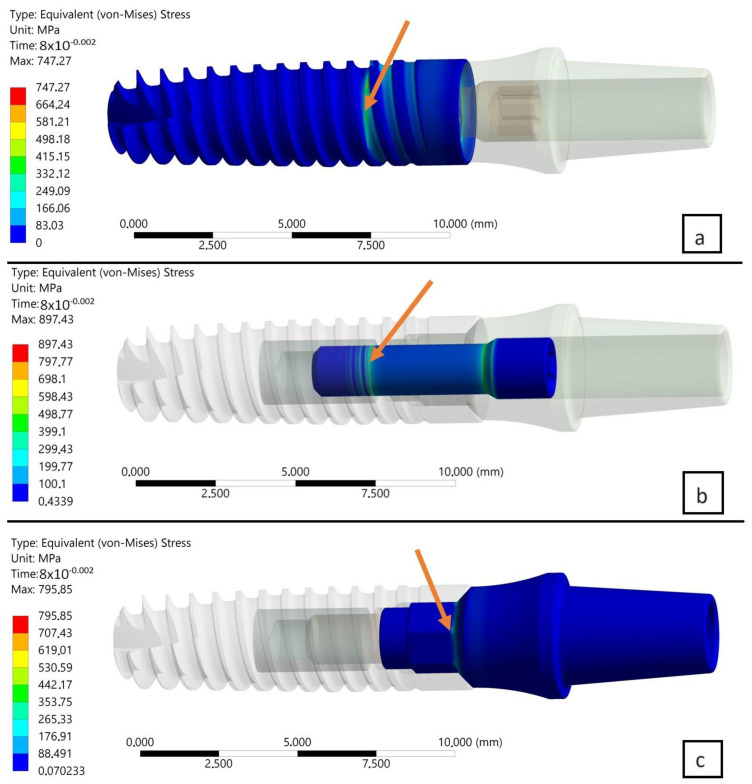
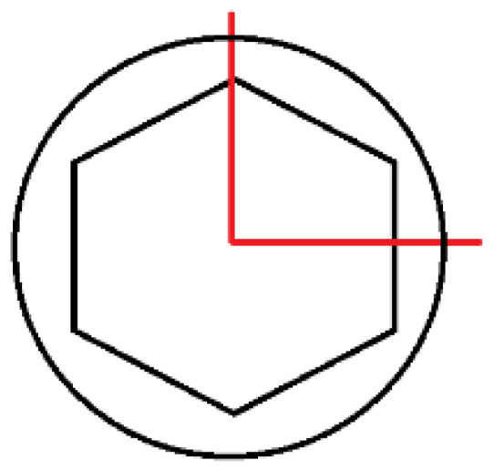
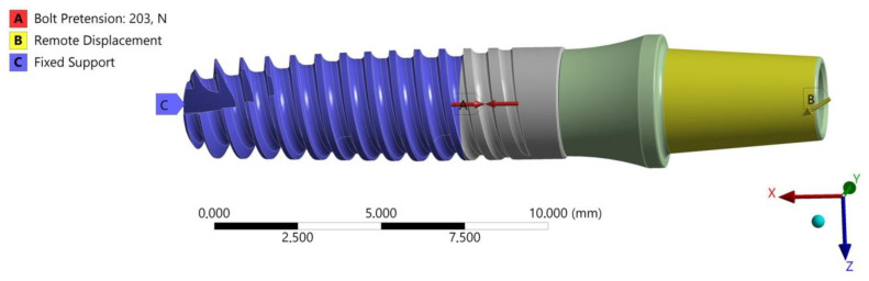
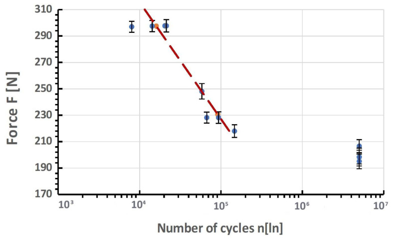
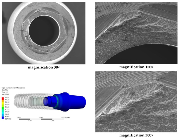
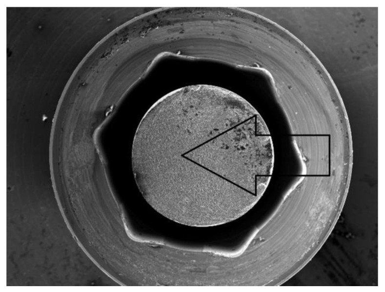
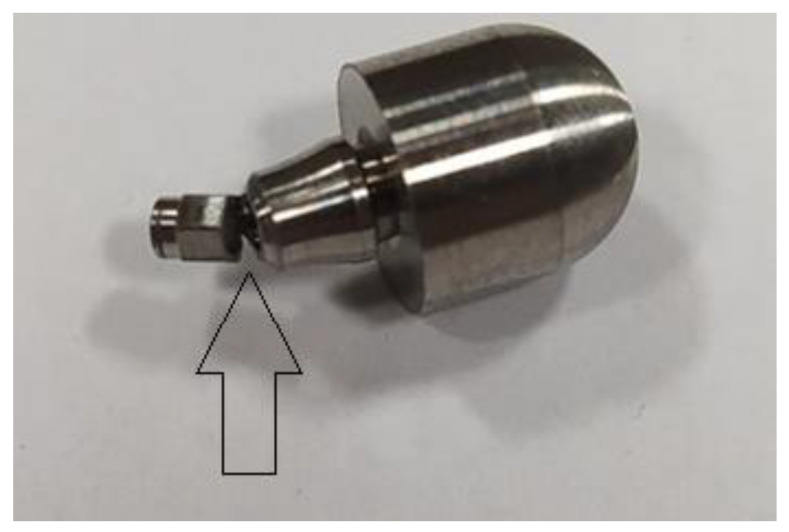
The study involved numerical FEA (finite element analysis) of dental implants. Based on this, fatigue tests were conducted according to the PN-EN 14801 standard required for the certification of dental products. Thanks to the research methodology developed by the authors, it was possible to conduct a thorough analysis of the impact of external and internal factors such as material, geometry, loading, and assembly of the dental system on the achieved value of fatigue strength limit in the examined object. For this purpose, FEM studies were based on identifying potential sites of fatigue crack initiation in reference to the results of the test conducted on a real model. The actions described in the study helped in the final evaluation of the dental system design process named by the manufacturer as INTEGRA OPTIMA 3.35. The objective of the research was to identify potential sites for fatigue crack initiation in a selected dental system built on the INTEGRA OPTIMA 3.35 set. The material used in the research was titanium grade 4. A map of reduced von Mises stresses was used to search for potential fatigue crack areas. The research [loading] was conducted on two mutually perpendicular planes positioned in such a way that the edge intersecting the planes coincided with the axis of the system. The research indicated that the connecting screw showed the least sensitivity (stress change) to the change in the loading plane, while the value of preload has a significant impact on the achieved fatigue strength of the system. In contrast, the endosteal implant (root) and the prosthetic connector showed the greatest sensitivity to the change in the loading plane. The method of mounting [securing] the endosteal implant using a holder, despite meeting the standards, may contribute to generating excessive stress concentration in the threaded part. Observation of the prosthetic connector in the Optima 3.35 system, cyclically loaded with a force of F ≈ 300 N in the area of the upper hexagonal peg, revealed a fatigue fracture. The observed change in stress peak in the dental connector for two different force application surfaces shows that the positioning of the dental system (setting of the socket in relation to the force action plane) is significantly decisive in estimating the limited fatigue strength.
Keywords: INTEGRA IMPLANTS; INTEGRA OPTIMA; PN-EN 14801; dental implant cracks; dental implant damage; finite element analysis.
Conflict of interest statement
The authors declare no conflicts of interest.
Figures
Similar articles
-
Effects of abutment screw preload in two implant connection systems: A 3D finite element study.J Prosthet Dent. 2019 Nov;122(5):474.e1-474.e8. doi: 10.1016/j.prosdent.2019.04.025. Epub 2019 Oct 4. J Prosthet Dent. 2019. PMID: 31590980
-
The dynamic natures of implant loading.J Prosthet Dent. 2009 Jun;101(6):359-71. doi: 10.1016/S0022-3913(09)60079-2. J Prosthet Dent. 2009. PMID: 19463663
-
Effects of abutment screw preload and preload simulation techniques on dental implant lifetime.JADA Found Sci. 2022;1:100010. doi: 10.1016/j.jfscie.2022.100010. Epub 2022 May 20. JADA Found Sci. 2022. PMID: 36704641 Free PMC article.
-
Mechanical strength and fracture point of a dental implant under certification conditions: A numerical approach by finite element analysis.J Prosthet Dent. 2018 Apr;119(4):611-619. doi: 10.1016/j.prosdent.2017.04.030. Epub 2017 Jul 15. J Prosthet Dent. 2018. PMID: 28720340
-
A comprehensive biomechanical evaluation of length and diameter of dental implants using finite element analyses: A systematic review.Heliyon. 2024 Feb 22;10(5):e26876. doi: 10.1016/j.heliyon.2024.e26876. eCollection 2024 Mar 15. Heliyon. 2024. PMID: 38434362 Free PMC article. Review.
Cited by
-
Mechanical and Material Analysis of 3D-Printed Temporary Materials for Implant Reconstructions-A Pilot Study.Biomedicines. 2024 Apr 15;12(4):870. doi: 10.3390/biomedicines12040870. Biomedicines. 2024. PMID: 38672224 Free PMC article.
-
Relationship Between Implant Connection and Implant Fracture: Systematic Review.Bioengineering (Basel). 2025 Mar 23;12(4):333. doi: 10.3390/bioengineering12040333. Bioengineering (Basel). 2025. PMID: 40281693 Free PMC article. Review.
-
Static and dynamic stress analysis of different crown materials on a titanium base abutment in an implant-supported single crown: a 3D finite element analysis.BMC Oral Health. 2024 May 10;24(1):545. doi: 10.1186/s12903-024-04328-0. BMC Oral Health. 2024. PMID: 38730391 Free PMC article.
References
-
- Gaddale R., Mishra S.K., Chowdhary R. Complications of screw- and cement-retained implant-supported full-arch restorations: A systematic review and meta-analysis. Int. J. Oral Implantol. 2020;13:11–40. - PubMed
LinkOut - more resources
Full Text Sources
Research Materials
