

Exploring the Beam Squint Effects on Reflectarray Performance: A Comprehensive Analysis of the Specular and Scattered Reflection of the Unit Cell
- PMID: 38474976
- PMCID: PMC10934141
- DOI: 10.3390/s24051438
Exploring the Beam Squint Effects on Reflectarray Performance: A Comprehensive Analysis of the Specular and Scattered Reflection of the Unit Cell
Abstract
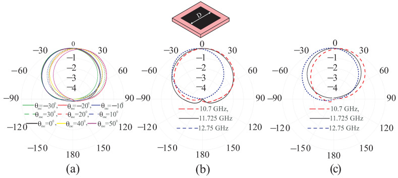
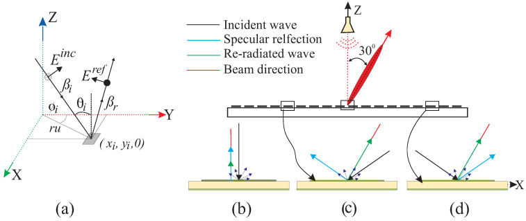
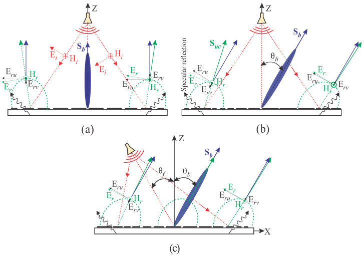
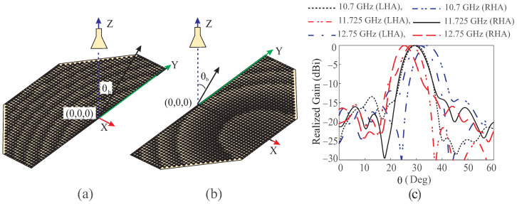
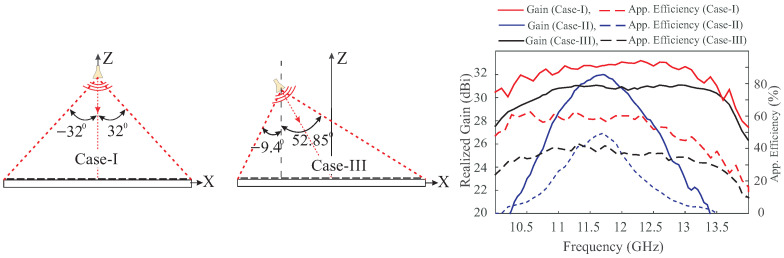
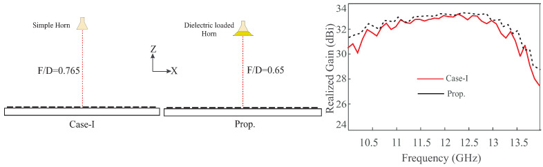
In this article, the phenomena of beam deviation in reflectarray is discussed. The radiation pattern of the unit cell, which plays a vital role in shaping the beam of the reflectarray, is analyzed by considering undesired specular and scattered reflections. These unwanted reflections adversely affect the pattern of the single unit cell, thereby reducing the overall performance of the reflectarray. To conduct our investigations, three cases of reflectarray-i.e., (i) a center-fed with broadside beam (Case-I), (ii) a center-fed with the beam at 30° (Case-II), and (iii) off-center-fed with the beam at 30° reciprocal to feed position with reference to the broadside direction (Case-III)-are simulated. Different degrees of beam deviation are analyzed in each reflectarray by assessing the radiation pattern of a single element. The simulation results shows that maximum of 0°, 3.4°, and 0.54° beam squint across the bandwidth found in Case-I, Case-II, and Case-III, respectively; this leads to aperture efficiencies of 31.2%, 11.9%, and 31.2%, respectively. The significance of specular reflections is further confirmed by half (left half and right half) aperture analysis of Case-II. This involves simulating the half-plane aperture illuminated by horn antenna, resulting in a distinct beam angle at the same frequency. However, deviations of -4.71 to +4.1 for the left half aperture and -1.82 to +1.1 for the right half aperture are noticed. Although the analysis specifically focuses on the three cases of the reflectarray, the proposed methodology is applicable to any type of reflectarray. The study presented in this work provides an important insight into the practical aspects of reflectarray operation, particularly in terms of quantifying undesirable effects that are normally overlooked in the design of this class of arrays. To achieve a good performance, a new design of the dielectric loaded horn feed is proposed. This design approach is both simple and applicable to any reflectarray, with the added benefit of maintaining a low profile for the RA. Moreover, this work holds significant potential for remote sensing satellite systems as beam deviation can adversely impact data collection accuracy and compromise observation precision, resulting in distorted images, reduced data quality, and overall hindrance to the system's performance in capturing reliable information.
Keywords: beam squint; reflectarray; scattered reflection; specular reflection.
Conflict of interest statement
Author Amir Altaf was employed by the company Millibeam. The remaining authors declare that the research was conducted in the absence of any commercial or financial relationships that could be construed as a potential conflict of interest.
Figures
Similar articles
-
Analysis and Design of an X-Band Reflectarray Antenna for Remote Sensing Satellite System.Sensors (Basel). 2022 Feb 3;22(3):1166. doi: 10.3390/s22031166. Sensors (Basel). 2022. PMID: 35161909 Free PMC article.
-
Gaussian to flat-top beam shaping in an off-axis reflective scenario by a millimeter-wave metasurface.Appl Opt. 2024 Mar 10;63(8):1908-1916. doi: 10.1364/AO.511269. Appl Opt. 2024. PMID: 38568628
-
Design and Analysis of Wideband Single-Layer Reflectarray Antenna for Remote Sensing and Environmental Monitoring.Sensors (Basel). 2025 Feb 5;25(3):954. doi: 10.3390/s25030954. Sensors (Basel). 2025. PMID: 39943593 Free PMC article.
-
Design and Validation of a Reflectarray Antenna with Optimized Beam for Ground Target Monitoring with a DVB-S-Based Passive Radar.Sensors (Basel). 2021 Aug 4;21(16):5263. doi: 10.3390/s21165263. Sensors (Basel). 2021. PMID: 34450720 Free PMC article.
-
Single-Layer Metasurface-Based Reflectarray Antenna with H-Shaped Slotted Patch for X-Band Communication.Nanomaterials (Basel). 2024 Sep 14;14(18):1495. doi: 10.3390/nano14181495. Nanomaterials (Basel). 2024. PMID: 39330652 Free PMC article.
References
-
- Han C., Zhang Y., Yang Q. A Broadband Reflectarray Antenna Using Triple Gapped Rings with Attached Phase-Delay Lines. IEEE Trans. Antennas Propagat. 2017;65:2713–2717. doi: 10.1109/TAP.2017.2679493. - DOI
-
- Xue F., Wang H., Yi M., Liu G., Dong X. Design of a Broadband Single-Layer Linearly Polarized Reflectarray Using Four-Arm Spiral Elements. IEEE Antennas Wirel. Propag. Lett. 2016;16:696–699. doi: 10.1109/LAWP.2016.2600374. - DOI
-
- Vosoogh A., Keyghobad K., Khaleghi A., Mansouri S. A highefficiency Ku-band reflectarray antenna using single-layer multiresonance elements. IEEE Antennas Wirel. Propag. Lett. 2014;14:891–894. doi: 10.1109/LAWP.2014.2321035. - DOI
-
- Qin P.Y., Guo Y.J., Weily A.R. Broadband reflectarray antenna using subwavelength elements based on double square meander-line rings. IEEE Trans. Antennas Propagat. 2015;64:378–383. doi: 10.1109/TAP.2015.2502978. - DOI
-
- Guo L., Tan P.K., Chio T.H. Bandwidth improvement of reflectarrays using single-layered double concentric circular ring elements on a subwavelength grid. Microw. Opt. Technol. Lett. 2014;56:418–421. doi: 10.1002/mop.28111. - DOI
Grants and funding
LinkOut - more resources
Full Text Sources
