

Inertial Measuring System to Evaluate Gait Parameters and Dynamic Alignments for Lower-Limb Amputation Subjects
- PMID: 38475055
- PMCID: PMC10934525
- DOI: 10.3390/s24051519
Inertial Measuring System to Evaluate Gait Parameters and Dynamic Alignments for Lower-Limb Amputation Subjects
Abstract
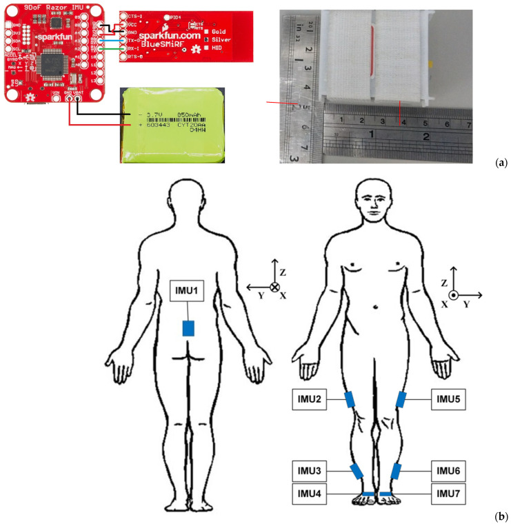
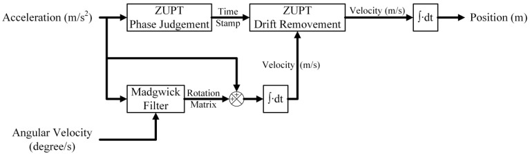
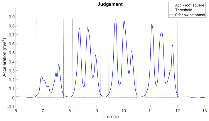
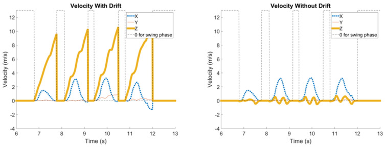
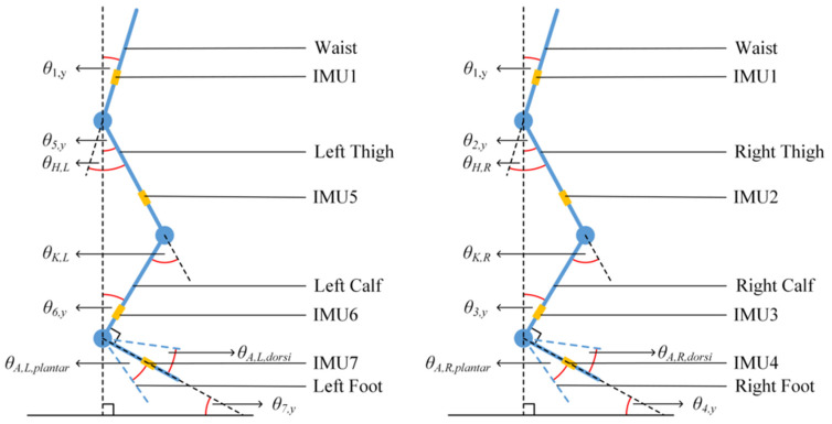
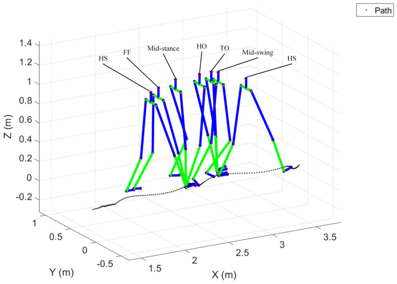
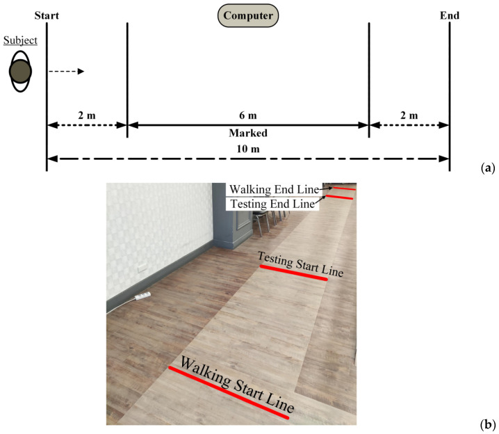
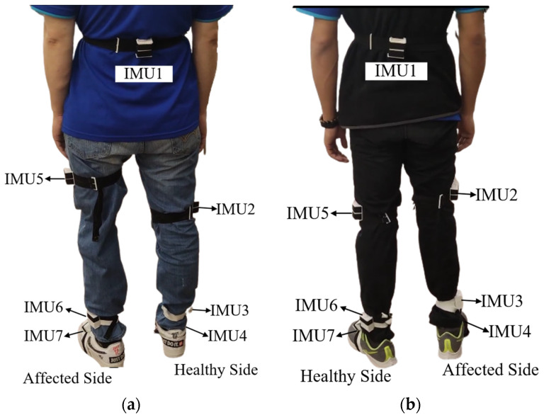
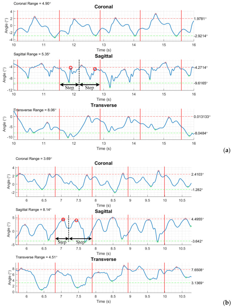
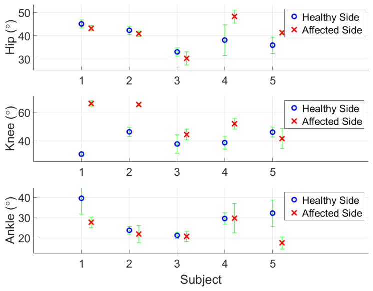
The study aims to construct an inertial measuring system for the application of amputee subjects wearing a prosthesis. A new computation scheme to process inertial data by installing seven wireless inertial sensors on the lower limbs was implemented and validated by comparing it with an optical motion capture system. We applied this system to amputees to verify its performance for gait analysis. The gait parameters are evaluated to objectively assess the amputees' prosthesis-wearing status. The Madgwick algorithm was used in the study to correct the angular velocity deviation using acceleration data and convert it to quaternion. Further, the zero-velocity update method was applied to reconstruct patients' walking trajectories. The combination of computed walking trajectory with pelvic and lower limb joint motion enables sketching the details of motion via a stickman that helps visualize and animate the walk and gait of a test subject. Five participants with above-knee (n = 2) and below-knee (n = 3) amputations were recruited for gait analysis. Kinematic parameters were evaluated during a walking test to assess joint alignment and overall gait characteristics. Our findings support the feasibility of employing simple algorithms to achieve accurate and precise joint angle estimation and gait parameters based on wireless inertial sensor data.
Keywords: Madgwick filtering; ZUPT; dynamic alignment; prosthetic gait analysis; wireless inertial measuring system.
Conflict of interest statement
The authors declare no conflicts of interest in this work.
Figures
Similar articles
-
Can high-functioning amputees with state-of-the-art prosthetics walk normally? A kinematic and dynamic study of 40 individuals.Ann Phys Rehabil Med. 2021 Jan;64(1):101395. doi: 10.1016/j.rehab.2020.04.007. Epub 2020 Aug 26. Ann Phys Rehabil Med. 2021. PMID: 32450271
-
Prosthetic gait of unilateral lower-limb amputees with current and novel prostheses: A pilot study.Clin Biomech (Bristol). 2020 Jan;71:59-67. doi: 10.1016/j.clinbiomech.2019.10.028. Epub 2019 Oct 31. Clin Biomech (Bristol). 2020. PMID: 31704536
-
The biomechanical response of persons with transfemoral amputation to variations in prosthetic knee alignment during level walking.J Rehabil Res Dev. 2016;53(6):1089-1106. doi: 10.1682/JRRD.2014.12.0311. J Rehabil Res Dev. 2016. PMID: 28355034 Free PMC article.
-
[Walking activity in prosthesis-bearing lower-limb amputees].Rev Chir Orthop Reparatrice Appar Mot. 2007 Apr;93(2):109-15. doi: 10.1016/s0035-1040(07)90213-5. Rev Chir Orthop Reparatrice Appar Mot. 2007. PMID: 17401283 French.
-
Effects of prosthetic mass and mass distribution on kinematics and energetics of prosthetic gait: a systematic review.Arch Phys Med Rehabil. 1999 Dec;80(12):1593-9. doi: 10.1016/s0003-9993(99)90336-2. Arch Phys Med Rehabil. 1999. PMID: 10597812
References
MeSH terms
Grants and funding
LinkOut - more resources
Full Text Sources
Medical
