Review
. 2024 Mar 3;10(5):e27264.
doi: 10.1016/j.heliyon.2024.e27264. eCollection 2024 Mar 15.

Digital hydraulic valves: Advancements in research

Affiliations
Review

Digital hydraulic valves: Advancements in research

Francesco Sciatti et al. Heliyon. .

Abstract

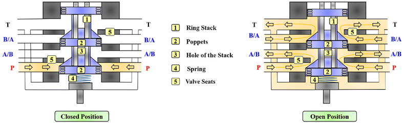
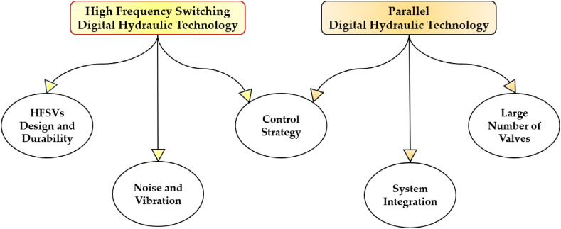
Despite the great advantages it offers, such as high-power density, precise control and large force output, conventional hydraulic valve control suffers from low energy efficiency due to substantial energy losses that occurs as the pressurized oil flows through the hydraulic circuit and its components, particularly the control-ones. Conventional hydraulic technology typically utilizes analogue spool valves, such as proportional and servovalves, as control components in various industrial and aeronautical applications where high precision and fast response are required. However, the use of these valves leads to high power dissipation, caused by the significant pressure drop across the small narrow passages uncovered during valve control. To maintain the relevance of hydraulic technology across industries, researchers are investigating a novel research field, also referred to as digital hydraulic technology. By using some digital concepts into hydraulic technology, the goal of this innovative research field is to replace conventional analogue spool valves with robust and low-cost digital On/Off valves, thus minimizing power losses and enhancing the overall efficiency of hydraulic systems. This paper presents a thorough review of the research advancements in digital hydraulic technology, with a specific focus on valve control. Firstly, the standard definition of digital hydraulic technology and its two main categories are introduced. Then, the operating principles and the digital approaches used to control digital hydraulic valves are examined. Afterwards, the digital hydraulic valve architectures developed over the years are reviewed, along with an in-depth analysis of their performance. Finally, the potential application scenarios, advantages and challenges with digital hydraulic valves are explored, highlighting potential areas for future research and development.


Conflict of interest statement

The authors declare that they have no known competing financial interests or personal relationships that could have appeared to influence the work reported in this paper.

Figures

Fig. 1
Fig. 1
Conventional hydraulic circuit: (1) Prime Mover; (2) Hydrostatic Pump; (3) Check Valve; (4) Accumulator; (5) Pressure Relief Valve; (6) Electrohydraulic Servovalve; (7) Linear Actuator; (8) Filter; (9) Heat Exchanger.
Fig. 2
Fig. 2
Conventional analogue spool valves and their relative ISO symbol: (a) Double-Stage Servovalve; (b) Single-Stage Servovalve; (c) Proportional Valve.
Fig. 3
Fig. 3
Main power losses in a conventional double-stage servovalve: (a) Internal Leakage of the main stage; (b) High pressure drops due to the small passages of the main stage; (c) Internal Leakage of the pilot stage.
Fig. 4
Fig. 4
Advantages of digital hydraulic technology compared to conventional hydraulic technology, adapted from Ref. [48].
Fig. 5
Fig. 5
A two-way two-position (2/2) digital hydraulic valve (poppet-type design) and its ISO symbols.
Fig. 6
Fig. 6
A scheme representing the control of digital hydraulic valves.
Fig. 7
Fig. 7
Classification of digital hydraulic valves based on the different control approaches involved.
Fig. 8
Fig. 8
Differences between the digital command signal used to control HFSVs: (a) PWM; (b) PFM; (c) invPFM; (d) DFM, adapted from Refs. [[70], [71], [72]].
Fig. 9
Fig. 9
Two way two-position (2/2) HFSV controlled with the PWM control approach.
Fig. 10
Fig. 10
Different behavior of an HFSV controlled by PWM technique, adapted from Ref. [70].
Fig. 11
Fig. 11
Performance Indicators of an HFSV: (a) Schematic Dynamic Movement; (b) Static Flow Curve, adapted from Ref. [75].
Fig. 12
Fig. 12
Four different DCV signals used to control a single HFSV: (a) Single-Voltage control; (b) Double-Voltage control; (c) Three-Voltage control; (d) Four-Voltage control, adapted from Ref. [75].
Fig. 13
Fig. 13
Four-way three-position (4/3) HFSV made up of four 2/2 HFSVs, adapted from Ref. [53].
Fig. 14
Fig. 14
Four-way three-position (4/3) HSFV composed of two 4/2 HFSVs [91].
Fig. 15
Fig. 15
A Digital Flow Control Unit (DFCU) made up of three two-way two-position (2/2) On/Off Valves: (a) Complete representation; (b) Simplified symbol (N represents the number of parallel connected switching valves); (c) Binary state table, adapted from Ref. [48].
Fig. 16
Fig. 16
Four-way three-position (4/3) DFCU Valve: (a) Complete representation; (b) Simplified representation, adapted from Refs. [94,95].
Fig. 17
Fig. 17
Comparison between analogue and digital hydraulic valves: a) Proportional Valve; b) 4/3 DFCU Valve, adapted from Ref. [48].
Fig. 18
Fig. 18
Fault-tolerance performance: (a) PCM coding; (b) PNM coding, adapted from Ref. [53].
Fig. 19
Fig. 19
Comparison between the PCM and the PNM control approaches: (a) DFCU made up of 3 On/Off Valves; (b) DFCU made up of 5 On/Off Valves; (c) DCU made up of 7 On/Off Valves, adapted from Ref. [53].
Fig. 20
Fig. 20
Redrawn schematic representation of the 2/2 HFSVs realized in Ref. [114]: (a) Basic Configuration; (b) Operating Principle to Open the Valve; (c) Operating Principle to Close the Valve.
Fig. 21
Fig. 21
Redrawn schematic representation of the 3/2 HFSV realized in Ref. [115]: (a) Basic Configuration: (b) Open Position; (c) Closed Position.
Fig. 22
Fig. 22
Redrawn schematic representation of the self-spinning rotary 3/2 HFSV proposed in Ref. [117]: (a) Cutaway illustration of spool and sleeve assembly; (b) Internal geometry of the spool; (c) Schematic representation of the rotary spool.
Fig. 23
Fig. 23
Redrawn schematic representation of the 2/2 HFSV realized in Ref. [118].
Fig. 24
Fig. 24
Redrawn schematic representation of the 2/2 HFSV realized in Refs. [[119], [120], [121]].
Fig. 25
Fig. 25
Redrawn schematic representation of the 3/2 HFSV realized in Refs. [123,124].
Fig. 26
Fig. 26
Redrawn schematic representation of the 2/2 HFSV realized in Ref. [125].
Fig. 27
Fig. 27
Redrawn working cycle of the 2/2 HFSV proposed in Ref. [126]: Closed Position (left); Open Position (middle); Closed Position (right).
Fig. 28
Fig. 28
2/2 HFSV proposed in Ref. [31]: Closed Position (left); Open Position (right).
Fig. 29
Fig. 29
4/2 HFSV proposed in Ref. [91]: Closed Position (left); Open Position (right).
Fig. 30
Fig. 30
HFSVs as pilot stage in a novel digital servovalve, adapted from Ref. [37].
Fig. 31
Fig. 31
Digital Hydraulic Buck Converters, adapted from Ref. [129].
Fig. 32
Fig. 32
Redrawn of the digital hydraulic system proposed in Ref. [134].
Fig. 33
Fig. 33
DFCU with sixteen On/Off valves in parallel developed by Paloniitty et al. [144]: (a) prototype; (b) utilized On/Off valve.
Fig. 34
Fig. 34
4/3 DFCU Valve with multiple On/Off valves in parallel developed by Ketonen et al. [147]: (a) prototype; (b) utilized On/Off valve.
Fig. 35
Fig. 35
DFCUs as pilot stage in a novel digital servovalve, adapted from Ref. [36].
Fig. 36
Fig. 36
DFCUs used to control independently velocity and pressure level of an actuator, adapted from Ref. [148].
Fig. 37
Fig. 37
DFCUs used to control a multi-chamber cylinder, adapted form [149].
Fig. 38
Fig. 38
Key challenges in High frequency switching and parallel digital hydraulic systems [153].

References

    1. Mays L.W. Environmental Fluid Mechanics; 2008. A Very Brief History of Hydraulic Technology during Antiquity; pp. 471–484. - DOI
    1. Papoutsidakis M., Chatzopoulos A., Papachristos D., Drosos C. Hydraulics and pneumatics: operational characteristics and control for modern industry applications. Int. J. Comput. Appl. Jun. 2019;178(25):31–40. doi: 10.5120/ijca2019919049. - DOI
    1. Mokyr J., et al. 2000. Knowledge, Technology, and Economic Growth during the Industrial Revolution.
    1. El-Din M.G., Rabi M. first ed. McGraw-Hill Education; New York: 2009. Fluid Power Engineering.https://www.accessengineeringlibrary.com/content/book/9780071622462 [Online]. Available:
    1. Moog . 2003. Proportional and Servo Valve Technology.

LinkOut - more resources