. 2024 Apr;33(4):e4965.
doi: 10.1002/pro.4965.

Mechanosensitive channel MscL gating transitions coupling with constriction point shift

Affiliations

Mechanosensitive channel MscL gating transitions coupling with constriction point shift

Mingfeng Zhang et al. Protein Sci. 2024 Apr.

Abstract

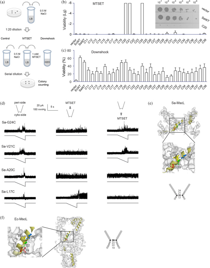
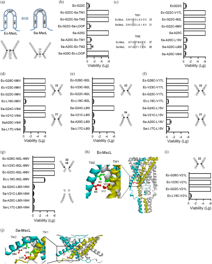
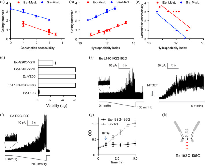
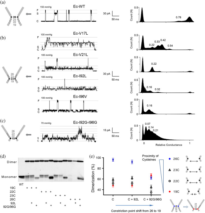
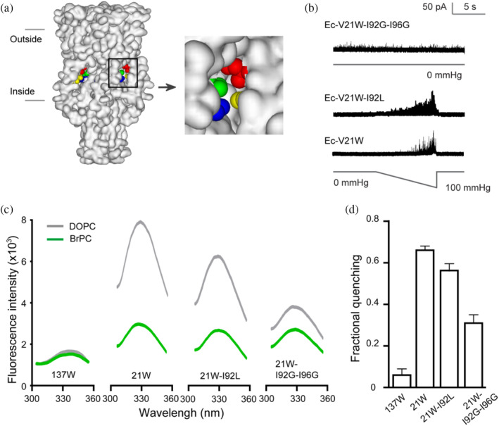
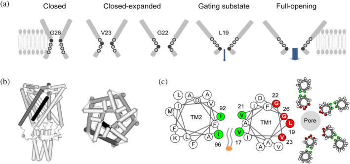
The mechanosensitive channel of large conductance (MscL) acts as an "emergency release valve" that protects bacterial cells from acute hypoosmotic stress, and it serves as a paradigm for studying the mechanism underlying the transduction of mechanical forces. MscL gating is proposed to initiate with an expansion without opening, followed by subsequent pore opening via a number of intermediate substates, and ends in a full opening. However, the details of gating process are still largely unknown. Using in vivo viability assay, single channel patch clamp recording, cysteine cross-linking, and tryptophan fluorescence quenching approach, we identified and characterized MscL mutants with different occupancies of constriction region in the pore domain. The results demonstrated the shifts of constriction point along the gating pathway towards cytoplasic side from residue G26, though G22, to L19 upon gating, indicating the closed-expanded transitions coupling of the expansion of tightly packed hydrophobic constriction region to conduct the initial ion permeation in response to the membrane tension. Furthermore, these transitions were regulated by the hydrophobic and lipidic interaction with the constricting "hot spots". Our data reveal a new resolution of the transitions from the closed to the opening substate of MscL, providing insights into the gating mechanisms of MscL.

Keywords: MscL; constriction point; gating pore; gating substate; gating transitions; mechanosensitive channel; protien-lipid interaction.


Conflict of interest statement

The authors declare that they have no conflict of interest.

Figures

FIGURE 1
FIGURE 1
A20 is the constriction point of Sa‐MscL channel. (a) Schematic representation of the in vivo viability assay. Control group, MTSET group (cultured with 1 mM MTSET), and Downshock group (diluted the culture into pure water) were determined. (b) Viability of Sa‐MscL cysteine mutants grow in the presence of MTSET. Cysteine mutants within the TM1 (11–39) are tested. The insets show the representative growth of 5 μL of each tenfold dilution (10−1 to 10−6) on LB plates. The viability data of MTSET treatment relative to the control in logarithmic scale were subjected to statistical analysis. (c) Viability of Sa‐MscL cysteine mutants under osmotic downshock. Cysteine mutants within the TM1 (11–39) are tested. (d) Spontaneous channel activities are dependent on the accessibility of MTSET from the periplasmic (middle panel) or cytoplasmic (right panel) side of Sa‐MscL channel. Channel activities without MTSET treatment are shown in left panel. In each recording, upper trace is the current, and lower trace is the negative pressure. (e) The diagram of the pore constriction of Sa‐MscL is composed of G24, V21, A20, and L17. Filled circle and bold number show the constriction point of A20. Side view of Sa‐MscL (Protein Data Bank code 3HZQ) with surface schematically shows G24 (blue), V21 (yellow), A20 (green), and L17 (red) in ball and stick style on an individual subunit in yellow. (f) The diagram of the pore constriction of Ec‐MscL is composed of G26, V23, G22, and L19. Filled circle and bold number show the constriction point of G26. Side view of a modeling of Ea‐MscL structure (Sukharev, Betanzos, et al., , derived from 2OAR) with surface schematically shows G26 (blue), V23 (yellow), G22 (green), and L19 (red) in ball and stick style on an individual subunit in yellow. SEM for each is shown, N = 5 independent experiments.
FIGURE 2
FIGURE 2
Identification of constricting “hot‐spots”. (a) The diagrams show the TM1, TM2, and LOOP domain (upper) and pore constriction (lower) of Ec‐MscL and Sa‐MscL, respectively. Filled cycle and bold number show the constriction point. (b) Replacements in the TMs but not LOOP domain affect the in vivo viability of the chimeras Ec‐G22C or Sa‐A20C. (c) Ec‐V17 (Sa‐L15) in the TM1, Ec‐I92, and Ec‐I96 (Sa‐L80 and Sa‐V84) in the TM2 induce the altered viability of Ec‐G22C or Sa‐A20C. (d–f) Viability assays show that exchanging the Ec‐I96 and the corresponding Sa‐V84 (d), the Ec‐I92 and the corresponding Sa‐L80 (e), the Ec‐V17 and the corresponding Sa‐L15 (f) lead to the movement of the constriction point. (g) Double mutants show further movement of the constriction point. (h) The proximity of Ec‐MscL V21 and I92, V17, and I96 revealed from a modeling of Ec‐MscL structure in closed state (Sukharev, Betanzos, et al., , derived from 2OAR). V21 and V17 are shown in ball and stick style in red and green, respectively, on the subunit in yellow, and I96 and I92 on the adjacent subunit in blue, are shown in ball and stick style in red and green, respectively. (i) Substitution of Ec‐V21 to corresponding Sa‐L19 (Ec‐V21L) shifts the constriction point from G26 to G22. (j) The proximity of I19 and L80, L15, and V84 is shown in Sa‐MscL structure (Protein Data Bank code 3HZQ). I19 and L15 are shown in ball and stick style in red and green, respectively, on the subunit in yellow, and V84 and L80 on the adjacent subunit in blue, are shown in ball and stick style in red and green, respectively. Samples were exposed to 1 mM MTSET in the absence of osmotic downshock, then to analyze the viability. Data presented as mean ± SEM, n = 6 independent experiments.
FIGURE 3
FIGURE 3
The occupation of constriction point at Ec‐L19 confers spontaneous gating. (a) MscL gates with less pressure upon the cytoplasmic shift of constriction point. (b) Hydrophilic substitution at V17, V21, I92, or I96 of Ec‐MscL increases the channel mechanosensitivity. (c) Hydrophilic substitution at V17, V21, I92, or I96 of Ec‐MscL leads to the cytoplasmic shift of the constriction point. (d) The hydrophobic substitution (V21I) rescues the viability defects of Ec‐G26C, whereas the hydrophilic substitution (I92G–I96G) causes loss of viability in Ec‐L19C. (e) Ec‐L19C–I92G–I96G shows the spontaneous activities and multiple channel openings in the presence of MTSET. (f) Ec‐I92G–I96G gates spontaneously. (g) Ec‐I92G–I96G exhibits poor liquid growth as compared to that of Ec‐MscL upon growth induction with IPTG (1 mM, indicated by arrow). (h) Schematic illustration displays the occupation of constriction point at L19 resulting in a leaking channel. Data presented as mean ± SEM, n = 6 independent experiments.
FIGURE 4
FIGURE 4
Gating transitions couple with the movement of constriction point. (a) Representative single channel current of Ec‐WT MscL recorded under negative pressure. The all‐point amplitude histogram in the right panel shows the gating substates. The peak positions shown by numbers represent the amplitude of substates relative to the amplitude of the fully open state. The diagram of the pore constriction of Ec‐MscL composed of G26, V23, G22, and L19 is shown on the left. Filled cycle and bold number show the constriction point in the diagram. C: closed state. S: substate. F: Fully open state. (b) Representative single‐channel current recorded under negative pressure and the all‐point amplitude histogram of Ec‐V17L, Ec‐V21L, Ec‐I92L, and Ec‐I96V. (c) Representative single‐channel current recorded under negative pressure and the all‐point amplitude histogram of Ec‐I92G–I96G. The multiple S0.07 substates are shown. (d) Representative western blotting showing disulfide bridge trapping of cysteine substitution at L19, G20, V23, and G26. (e) Summary analysis of percentage of dimerization in total MscL protein (Mean ± SEM, n = 6 western blotting). 26C (blue circle), 23C (black triangle), 22C (black circle), and 19C (red circle). Diagram shows the distance between cysteines changes upon the movement of constriction point. The distance between 26C, 23C, and 22C were increased upon the shift of constriction point from G26 to L19, whereas the distance between 19C was decreased.
FIGURE 5
FIGURE 5
Interaction of lipids and Ec‐V21W in the gating process. (a) Side view of the protein surface of Ec‐MscL in closed state (Sukharev, Betanzos, et al., , derived from 2OAR). The horizontal lines show the approximate positions of two sides of the membrane. V17 (blue), V21 (green), and the adjacent I92 (red), and I96 (yellow) are shown in space‐fill style in the cavity in the enlargement of the square box. (b) Single channel recordings show the pressure‐dependent MscL activity of Ec‐V21W and EC‐V21W–I92L, and spontaneous activity of Ec‐V21W–I92G–I96G. (c) Representative tryptophan fluorescence emission of MscL mutants reconstituted in brominated lipids (BrPC, green) or nonbrominated PC (DOPC, gray). (d) I92L and I92G–I96G substitutions decrease the BrPC quenching of 21 W fluorescence intensity (Mean ± SEM, n = 5 reconstitutions).
FIGURE 6
FIGURE 6
A model of MscL gating transition. (a) Schematic illustration displays the constriction point shift in the gating process, coupled with the expansion of pore constriction region. Filled cycle and bold number show the constriction point. Arrows indicate the ion permeation. (b) Schematic representations of Ec‐MscL structure in the closed state (Sukharev, Betanzos, et al., , derived from 2OAR). Left: side view of the MscL pentamer. Right: top view from the periplasmic. TM1 (black) of an individual MscL subunit, and TM2 (dark gray) of adjacent subunit are shown. (c) Helical wheel diagrams showing the lipids–protein interaction. The constriction “hot‐spots” (blue) form the hydrophobic pocket at the interfacial region of TM1–TM2. Constriction points (red) line the constriction of the pore. The penetration of lipids into the hydrophobic pocket is shown.

Similar articles

References

    1. Anishkin A, Chiang C, Sukharev S. Gain‐of‐function mutations reveal expanded intermediate states and a sequential action of two gates in MscL. J Gen Physiol. 2005;125:155–170. - PMC - PubMed
    1. Bartlett J, Levin G, Blount P. An in vivo assay identifies changes in residue accessibility on mechanosensitive channel gating. Proc Natl Acad Sci USA. 2004;101:10161–10165. - PMC - PubMed
    1. Bartlett J, Li Y, Blount P. Mechanosensitive channel gating transitions resolved by functional changes upon pore modification. Biophys J. 2006;91:3684–3691. - PMC - PubMed
    1. Batiza A, Kuo M, Yoshimura K, Kung C. Gating the bacterial mechanosensitive channel MscL in vivo. Proc Natl Acad Sci USA. 2002;99:5643–5648. - PMC - PubMed
    1. Bavi N, Cortes D, Cox C, Rohde P, Liu W, Deitmer J, et al. The role of MscL amphipathic N terminus indicates a blueprint for bilayer‐mediated gating of mechanosensitive channels. Nat Commun. 2016;22:11984–11997. - PMC - PubMed

MeSH terms

LinkOut - more resources