. 2024 Apr 11;21(2):026039.
doi: 10.1088/1741-2552/ad357f.

Computational modeling of dorsal root ganglion stimulation using an Injectrode

Affiliations

Computational modeling of dorsal root ganglion stimulation using an Injectrode

Sauradeep Bhowmick et al. J Neural Eng. .

Abstract

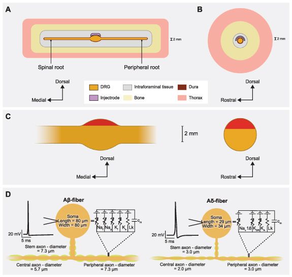
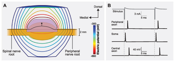
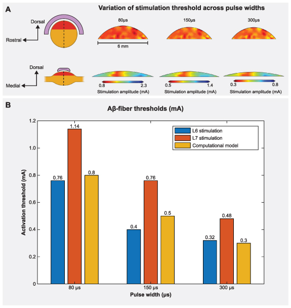
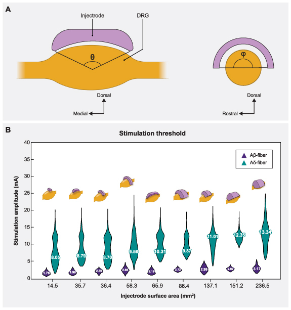
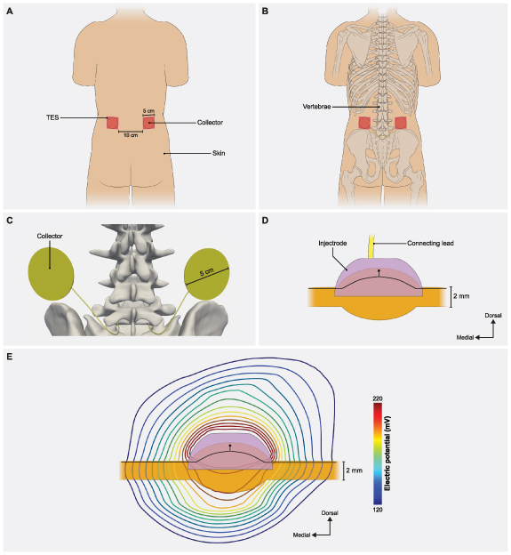
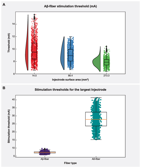
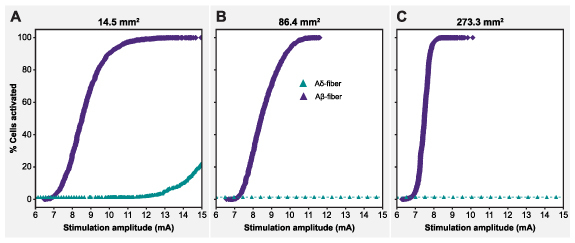
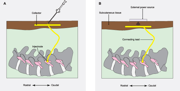
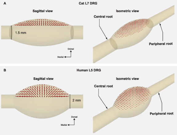
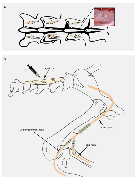
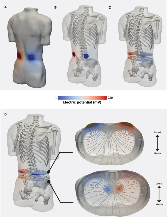
Objective.Minimally invasive neuromodulation therapies like the Injectrode, which is composed of a tightly wound polymer-coated Platinum/Iridium microcoil, offer a low-risk approach for administering electrical stimulation to the dorsal root ganglion (DRG). This flexible electrode is aimed to conform to the DRG. The stimulation occurs through a transcutaneous electrical stimulation (TES) patch, which subsequently transmits the stimulation to the Injectrode via a subcutaneous metal collector. However, it is important to note that the effectiveness of stimulation through TES relies on the specific geometrical configurations of the Injectrode-collector-patch system. Hence, there is a need to investigate which design parameters influence the activation of targeted neural structures.Approach.We employed a hybrid computational modeling approach to analyze the impact of Injectrode system design parameters on charge delivery and neural response to stimulation. We constructed multiple finite element method models of DRG stimulation, followed by the implementation of multi-compartment models of DRG neurons. By calculating potential distribution during monopolar stimulation, we simulated neural responses using various parameters based on prior acute experiments. Additionally, we developed a canonical monopolar stimulation and full-scale model of bipolar bilateral L5 DRG stimulation, allowing us to investigate how design parameters like Injectrode size and orientation influenced neural activation thresholds.Main results.Our findings were in accordance with acute experimental measurements and indicate that the minimally invasive Injectrode system predominantly engages large-diameter afferents (Aβ-fibers). These activation thresholds were contingent upon the surface area of the Injectrode. As the charge density decreased due to increasing surface area, there was a corresponding expansion in the stimulation amplitude range before triggering any pain-related mechanoreceptor (Aδ-fibers) activity.Significance.The Injectrode demonstrates potential as a viable technology for minimally invasive stimulation of the DRG. Our findings indicate that utilizing a larger surface area Injectrode enhances the therapeutic margin, effectively distinguishing the desired Aβactivation from the undesired Aδ-fiber activation.

Keywords: chronic pain; computer simulation; dorsal root ganglion; electric stimulation; injectrode; neuromodulation.


Conflict of interest statement

M F, A J S, and K A L are co-founders of Neuronoff, Inc. S N, D J W, J K T, A J S, K A L, S F L, and M F are equity holders for Neuronoff Inc. A J S, M F, and S N are employees at Neuronoff, Inc. K A L is a scientific board member and has stock interests in NeuroOne Medical Inc. K A L is also a paid member of the scientific advisory board of Abbott, Cala Health, Blackfynn, Battelle, Neuronoff and Presidio Medical, and a paid consultant for the Alfred Mann Foundation, ONWARD, Restora Medical, Neuronoff and CVRx. KAL is a co-founder of NeuraWorx. D J W is a scientific board member for NeuroOne Medical Inc. and a paid consultant for Innervace. N V is currently an employee at Presidio Medical, developing SCS therapy for pain. N V was a contractor for Abbott Neuromodulation and a part-time employee of BioCircuit Technologies when the work was performed. N V is currently a consultant for NeuraWorx. J K T is a consultant for Presidio Medical. R D G is currently a consultant for Nalu Medical, Inc. S F L holds stock options, serves on the scientific advisory board, and receives research support from Presidio Medical Inc., and is a shareholder at Hologram Consultants, LLC. S F L also receives research support from Abbott Neuromodulation and Medtronic, Inc. None of these associations outside those to Neuronoff are directly relevant to the work presented in this manuscript. The rest of the authors have no conflicts to declare.

Figures

Figure 1.
Figure 1.
Representative schematic of our finite element method (FEM) model of DRGS. We developed an FEM model of a DRG and surrounding anatomy. Two separate versions of this model were developed and scaled to fit dimensions of the feline L7 DRG and human L5 DRG. (A) Side view of the DRG with the Injectrode oriented above the ganglion. (B) Cross-sectional view through the middle of the DRG and Injectrode. (C) Red-shaded regions indicate the locations of the somata of primary sensory neurons in sagittal and transverse DRG cross sections. (D) Multicompartment models of primary sensory neurons, representing the pseudounipolar morphology of a large-diameter myelinated Aβ-fiber and a smaller-diameter thinly myelinated Aδ-fiber. An example action potential from each model neuron is shown on the left. The equivalent circuit diagram with active ion conductances included in the nodal, initial segment, and soma compartments is shown on the right.
Figure 2.
Figure 2.
Coupling the finite element method (FEM) model of a human L5 DRG to the multicompartment models of primary sensory neurons. (A) Isopotential lines of the extracellular potentials generated by leading cathodic monopolar DRGS calculated from the FEM model. An example primary sensory neuron trajectory is shown in black with the soma below the Injectrode. (B) Time-dependent transmembrane voltages resulting from stimulating an example Aβ-fiber with a cathodic stimulus having a pulse amplitude of 6 mA, pulse width of 300 µs, and pulse frequency of 40 Hz. The action potential initiates near the soma and then propagates into the peripheral and central axons, as shown in the three traces.
Figure 3.
Figure 3.
DRGS amplitudes required to elicit one or more action potentials (activation threshold) in Aβ-fibers for stimulation with an Injectrode in the feline model. (A) The contour plots show variation of activation thresholds along the dorsal-rostral plane and the dorsal-medial plane for three different pulse widths. The red shaded region indicates the location of the somata of the primary sensory neurons, enclosed by the Injectrode at the top. The dorsal-rostral cross section (top) is taken along the midline of the dorsal-medial view (bottom), marked by a dashed line, and vice versa. (B) Comparison of minimum activation thresholds generated by our computational model with the ECAP thresholds from the acute experiments (for two lumbar levels) across three different pulse widths [28].
Figure 4.
Figure 4.
Sagittal and transverse cross sections of the DRG and the Injectrode indicating the various angles of coverage of the Injectrode and the corresponding mean activation thresholds. (A) The angles in both planes (θ,ϕ) varied from 30° to 150° at an interval of 60°, thus generating a total of nine models. (B) Plots showing comparison between the distribution of activation thresholds of Aβ- and Aδ-fibers generated by the various Injectrode geometries with the mean values inset and the corresponding Injectrode geometry at the top of each violin plot.
Figure 5.
Figure 5.
Full-body model with truncated arms, legs and neck with a charge delivery system mimicking clinical implementation of an Injectrode system. (A) Dorsal view of the body with transcutaneous electrical stimulator (TES) patch electrodes visible on the skin surface at the L2 vertebral level. In a bipolar configuration, one TES electrode serves as an active terminal and the other TES electrode is grounded. (B) Collectors are placed directly under the TES patch to receive some of the charge delivered to the TES electrodes. (C) The collectors deliver charge to the Injectrode using a connecting lead made of the same material and inserted in the spinal cavity using an interlaminar approach. (D) A side view of the Injectrode, DRG, and the connecting lead. The Injectrode sits right on top of the dorsal aspect of the DRG. An example primary sensory neuron trajectory is shown in black. (E) Isopotential lines of the potential field generated by the bipolar TES-collector-Injectrode system near the DRG with an example primary sensory neuron shown in black.
Figure 6.
Figure 6.
The effect of Injectrode size on activation thresholds with the bipolar Injectrode DRGS configuration in the full-body model. (A) Raincloud plots show the variation of stimulation amplitudes for the entire population of model Aβ-fibers within the DRG. (B) Activation thresholds for the entire populations of Aβ- and Aδ-fibers using the Injectrode with the largest surface area (273.3 mm2) considered in this study.
Figure 7.
Figure 7.
Recruitment curves of the Aβ- and Aδ-fibers for the Injectrodes of three different surface areas; with the maximum amplitude corresponding to the amplitude necessary to activate the entire Aβ-fiber population.
Figure A1.
Figure A1.
Illustrations depicting the 18 ga needle-based deployment of the Injectrode and the charge delivery mechanism based on an external power source. A simple needle-based placement of the device minimizes or eliminates the need for surgery. Once placed, the Injectrode creates a low impedance path for electrical signals from just underneath the skin down to the neural target. (A) Needle used to deploy the Injectrode on the DRG and protruded back to the subcutaneous layer to create a deposition of a similar material, which acts as the collector. (B) External power source is used to wirelessly transfer charge to the collector.
Figure A2.
Figure A2.
Locations of PSN somata. The plots above show the locations of the somata for each model neuron used in this study. (A) We placed the somata along the dorsal half of the feline L7 DRG. Sagittal and isometric views of the somata of 1355 neurons. (B) We placed somata along the dorsal half of the human L5 DRG. Sagittal and Isometric views of the human L5 DRG populated with the somata of 1378 neurons.
Figure A3.
Figure A3.
Experimental setup for the acute experiments in our prior work. (A) Exposure of the DRG by either a partial laminectomy or a burr hole. Inset: Injectrode delivered through a burr hole over the DRG. (B) We placed an Injectrode on top of a DRG to apply the stimulation. We recorded antidromic evoked compound action potentials using spiral nerve cuffs placed on the sciatic, tibial, and common peroneal nerves. Cuff contacts were 4 mm apart. Adapted from [28]. © The Author(s). Published by IOP Publishing Ltd CC BY 4.0.
Figure A4.
Figure A4.
Potential field generated during DRGS using the Injectrode-collector-patch system. (A) Electric potential field due to stimulation at the TES patch. The active and return terminals are marked by red and blue, respectively. (B) Potential field inside the body with the collector-Injectrode system. (C) Cross-sectional slices along the center of the collector and the center of the Injectrode demonstrates the potential field in those two planes. (D) Isopotential lines in the two cross sectional slice planes at the rostrocaudal level of the collector and the Injectrode. Both views are magnified separately along the axial plane. The axial view of the two sets of isopotential lines are shown in the two subset plots.

Update of

References

    1. Kuehn B M. Chronic pain prevalence. JAMA. 2018;319:2471. doi: 10.1001/jama.2018.7441. - DOI - PubMed
    1. Gaskin D J, Richard P. The economic costs of pain in the United States. J. Pain. 2012;13:715–24. doi: 10.1016/j.jpain.2012.03.009. - DOI - PubMed
    1. Graham R D, Sankarasubramanian V, Lempka S F. Dorsal root ganglion stimulation for chronic pain: hypothesized mechanisms of action. J. Pain. 2021;23:196–211. doi: 10.1016/j.jpain.2021.07.008. - DOI - PMC - PubMed
    1. Graham R D, Bruns T M, Duan B, Lempka S F. Dorsal root ganglion stimulation for chronic pain modulates Aβ-fiber activity but not C-fiber activity: a computational modeling study. Clin. Neurophysiol. 2019;130:941–51. doi: 10.1016/j.clinph.2019.02.016. - DOI - PMC - PubMed
    1. Graham R D, Bruns T M, Duan B, Lempka S F. The effect of clinically controllable factors on neural activation during dorsal root ganglion stimulation. Neuromodulation. 2021;24:655–71. doi: 10.1111/ner.13211. - DOI - PubMed

Publication types