Review
. 2023 Jan 20;4(1):011303.
doi: 10.1063/5.0130762. eCollection 2023 Mar.

Microfluidic techniques for mechanical measurements of biological samples

Affiliations
Review

Microfluidic techniques for mechanical measurements of biological samples

Paul F Salipante. Biophys Rev (Melville). .

Abstract

The use of microfluidics to make mechanical property measurements is increasingly common. Fabrication of microfluidic devices has enabled various types of flow control and sensor integration at micrometer length scales to interrogate biological materials. For rheological measurements of biofluids, the small length scales are well suited to reach high rates, and measurements can be made on droplet-sized samples. The control of flow fields, constrictions, and external fields can be used in microfluidics to make mechanical measurements of individual bioparticle properties, often at high sampling rates for high-throughput measurements. Microfluidics also enables the measurement of bio-surfaces, such as the elasticity and permeability properties of layers of cells cultured in microfluidic devices. Recent progress on these topics is reviewed, and future directions are discussed.


Conflict of interest statement

The authors have no conflicts to disclose.

Figures
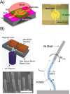
FIG. 1.
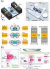
FIG. 1.
(a) A film bulk acoustic resonator using a ZnO film designed by Chen et al. for blood viscosity measurements. Reproduced with permission from Chen et al., Sensors 17, 1015 (2017). Copyright 2017 authors, licensed under a Creative Commons Attribution (CC BY) License. (b) Magnetically actuated flexible microposts were used by Judith et al. to measure the viscosity through hydrodynamic interactions. Reproduced with permission from Judith et al., PLoS One 13, e0200345 (2018). Copyright 2018 authors, licensed under a Creative Commons Attribution (CC BY) License.
FIG. 2.
FIG. 2.
(a) A paper based device developed by Li et al. for measuring the coagulation of blood by related the travel time of the fluid front to the viscosity. The device was later tested as a point-of-care diagnostic device by Hegener et al. Reproduced from Li et al., Biomicrofluidics 12, 014110 (2018) with the permission of AIP Publishing LLC. (b) A paper based device by Jang et al. used two paper strips for faster capillary driven flow to measure fluid viscosity without requiring a separate surface tension measurement. Reproduced with permission from Jang et al., Sens. Actuators, B 319, 128240 (2020). Copyright 2020 Elsevier B.V. (c) A paper-based device developed by Kang et al. uses the color of two mixed streams to measure the relative flow rates of the stream and determine viscosity. Reproduced with permission from Kang et al., Anal. Chem. 91, 4868 (2019). Copyright 2019 American Chemical Society. (d) A capillary-driven flow device designed by Lee et al. was used to measure zebrafish blood viscosity by tracking the interface velocity. Reproduced with permission from Lee et al., Sci. Rep. 7, 1980 (2017). Copyright 2017 authors, licensed under a Creative Commons Attribution (CC BY) License.
FIG. 3.
FIG. 3.
(a) A "smart" pipette designed by Oh et al. with an air chamber to deliver pneumatic pressure to microcapillary channels in a 3D-printed microfluidic for viscosity measurement at different flow rates. Reproduced with permission from S. Oh and S. Choi, Micromachines 9, 314 (2018). Copyright 2018 Authors, licensed under a Creative Commons Attribution (CC BY) License. (b) A meniscus method for viscosity measurements by Solomon et al. to measure flow rate through a microchannel using a smartphone camera. Reproduced with permission from Solomon et al., Rheol. Acta 55, 727 (2016). Copyright 2016 Springer-Verlag Berlin Heidelberg. (c) A microfluidic rheometer fabricated by Mendez-Mora et al. with gold electrodes across a microfluidic channel used to track the fluid meniscus for flow rate measurements. Reproduced with permission from Méndez-Mora et al., Micromachines 12, 726 (2021). Copyright 2021 authors, licensed under a Creative Commons Attribution (CC BY) License. (d) A small volume rheometer designed by Salipante et al. uses real-time mesniscus tracking using a linear image sensor and a pneumatic valve to reversibly drive flow through a microcapillary. Reproduced with permission from Salipante et al., Rheol. Acta 61, 309 (2022). Copyright 2022. This is a U.S. government work and not under copyright protection in the U.S.; foreign copyright protection may apply.
FIG. 4.
FIG. 4.
(a) A co-flowing device made continuous measurement of blood viscosity by tracking the position of the interface between the sample and reference fluid. Reproduced with permission from Yeom et al., Sci. Rep. 6, 24994 (2016). Copyright 2016Authors, licensed under a Creative Commons Attribution (CC BY) License. (b) A co-flowing device by Kim et al. used a smartphone camera to track the interface position to determined the viscosity of blood and plasma samples. Reproduced with permission from Kim et al., Opt. Lasers Eng. 104, 237 (2018). Copyright 2018 Elsevier Ltd. (c) A suspended micro-membrane with folded beams by Liu et al. measured viscosity by relating deflection of the membrane to the fluid stress. Reproduced with permission from Liu et al., Micromachines 11, 934 (2020). Copyright 2020 authors, licensed under a Creative Commons Attribution (CC BY) License. (d) A co-flowing viscometer by Mehri et al. tracked aggregation of RBC at different flow rates. Reproduced with permission from Mehri et al., PLoS ONE 13, 7 (2018). Copyright 2018 authors, licensed under a Creative Commons Attribution (CC BY) License.
FIG. 5.
FIG. 5.
(a) A multilayer microfluidic device by Wehrman et al. to control release of components into a chambers where phase transitions between gel and sol transition are measured with microrheology tracking Reproduced with permission from Wehrman et al., J. Rheol. 62, 437 (2018). Copyright 2018 The Society of Rheology. (b) Mean-squared-displacement measurements from microparticle tracking by Wehrman et al. in covalently adaptable hydrogels during phase changes. Reproduced with permission from Wehrman et al., Lab Chip 17, 2085–2094 (2017). Copyright 2017 Royal Society of Chemistry.
FIG. 6.
FIG. 6.
(a) A two-channel device by Kim et al. with a differential pressure sensor to measure the extra pressure drop from a converging channel used to measure extensional viscosity. Reproduced with permission from S. G. Kim and H. S. Lee, Macromolecules 52, 9585 (2019). Copyright 2019 American Chemical Society. (b) An optimized cross-slot device by Haward et al. to create a larger region of extensional flow for extensional rheology measurements. Reproduced from Haward et al., Biomicrofluidics 7, 044108 (2013) with the permission of AIP Publishing LLC. (c) A microfluidic flow focusing device by Metaxas et al. used to measure extensional rheology by tracking the thinning of the fluid filament. Reproduced with permission from Metaxas et al., Phys. Rev. Fluids 5, 113302 (2020). Copyright 2020 American Physical Society.
FIG. 7.
FIG. 7.
(a) The time-dependent shape deformation and shear stress used of cells flowed through a constriction by Fregin et al for high-throughput cytometry to measure viscoelastic properties. Reproduced with permission from Fregin et al., Nat. Commun. 10, 415 (2019). Copyright 2019 Authors, licensed under a Creative Commons Attribution (CC BY) License. (b) A microfluidic nozzle by Rubio et al. formed by melt-shaping a glass capillary used to measure elastic properties of RBCs by tracking deformation in the nozzle. Reproduced with permission from Rubio et al., Polymers 14, 2784 (2022). Copyright 2022 Authors, licensed under a Creative Commons Attribution (CC BY) License. (c) An optimized constriction geometry developed by Liu et al. to create a region of uniform extension used for measurements of DNA and actin filaments under extension. Reproduced with permission from Liu et al., Soft Matter 16, 9844–9856 (2020). Copyright 2020 Royal Society of Chemistry.
FIG. 8.
FIG. 8.
(a) A cross-slot geometry used by Armistead et al. to measure the nonlinear viscoelastic deformation and failure points for different types of circulating cancer cells. Reproduced with permission from Armistead et al., Biophys. J. 116, 1127–1135 (2019). Copyright 2019 Authors, licensed under a Creative Commons Attribution (CC BY) License. (b) A Stokes trap used by Kumar et al. to trap and control extensional flow to induce large asymmetric dumbbell shape deformation of vesicle. Reproduced with permission from D. Kumar and C. M. Schroeder, Langmuir 37, 13976–13984 (2021). Copyright 2021 American Chemical Society.
FIG. 9.
FIG. 9.
(a) The transit time of cells through a parallel array of microconstrictions used by Lange et al. for high-throughput measurements of cell viscoelastic properties. Reproduced with permission from Lange et al., Biophys. J. 109, 26–34 (2015). Copyright 2015 Biophysical Society. (b) The protrusion length of the cell into the microconstriction combined with the measured pressure drop was used by Chen et al. to measure the viscoelastic properties of cells. Reproduced with permission from Chen et al., Methods X 8, 101247 (2021). Copyright 2021 Authors, licensed under a Creative Commons Attribution (CC BY) License. (c) Automated image analysis method by Nyberg et al. to perform shape analysis on leukemia cells driven through a microcontrictions is used to measure viscoelastic properties of the cells. Reproduced with permission from Lange et al., Biophys. J. 112, 1472–1480 (2017). Copyright 2017 Biophysical Society.
FIG. 10.
FIG. 10.
(a) Electrodes in a microfluidic channel by Qiang et al. produced dielectrophoretic force on cells to measured viscoelastic properties of the cells under cyclical loading. Reproduced with permission from Qiang et al., Acta Biomater. 57, 352–362 (2017). Copyright 2017 Acta Materialia Inc. (b) A device by Yang et al. used to periodically trap and deform multiple cells using dielectrophoretic force for high-throughput viscoelastic measurements. Reproduced with permission from Yang et al., iScience 25, 104275 (2022). Copyright 2022 Authors, licensed under a Creative Commons Attribution (CC BY) License.
FIG. 11.
FIG. 11.
(a) Two optical fibers are fabricated in a microfluidic channel by Huang et al. to deform cells passing through using optical stretching. Reproduced with permission from Huang et al., Microsyst. Nanoeng. 6, 57 (2020). Copyright 2020 Authors, licensed under a Creative Commons Attribution (CC BY) License. (b) An optical tweezer used by Yao et al. temporarily traps flowing RBCs and the stretch induced by the flow past the pinned cell is used to measure cell stiffness. Reproduced with permission from Yao et al., Lab Chip 20, 601–613 (2020). Copyright 2020 Authors, licensed under a Creative Commons Attribution (CC BY) License.
FIG. 12.
FIG. 12.
(a) Two arrays of pillars in a microfluidic device by Sofela et al. measures the forces exerted by the trapped C. elegans by tracking large deformation of pillars. Reproduced with permission from Sofela et al., PLoS One 16, e0246496 (2021). Copyright 2021 authors, licensed under a Creative Commons Attribution (CC BY) License. (b) An array of pillars used by Rahman et al. to measure the C. elegans forces by tracking the deflection of pillars during locomotion. Reproduced with permission from Rahman et al., Lab Chip 18, 2187–2201 (2018). Copyright 2018 Royal Society of Chemistry.
FIG. 13.
FIG. 13.
(a) Transmission microscopy is used by Paquet-Mercier et al. to track structures imaged in biofilms to measure the film viscosity under flow over time. A rapid increase in viscosity was observed at different times depending on salt concentration. Reproduced with permission from Paquet-Mercier et al., Lab Chip 16, 4710–4717 (2016). Copyright 2016 Royal Society of Chemistry. (b) The onset of sloughing events is measured by Greener et al. using optical density measurements to determined the biofilm height and probe yielding behavior of the biofilms under different conditions. Reproduced from Greener et al., Biomicrofluidics 10, 064107 (2016) with the permission of AIP Publishing LLC.
FIG. 14.
FIG. 14.
(a) A multilayer device by Frost et al. cultured epithelial and endothelial cells on either side to measured permeability by tracking fluorophore transport across the membrane to model the lung-blood barrier. Reproduced with permission from Frost et al., Micromachines 10, 533 (2019). Copyright 2019 authors, licensed under a Creative Commons Attribution (CC BY) License. (b) An method by Nguyen et al. actuated particles embedded on a cell layer by acoustic force as a probe of the viscoelastic properties of the cell layer. The particle oscillations are tracked using microscopy and create a spatial information about the cell layer properties. Reproduced with permission from Nguyen et al., Lab Chip 21, 1929–1947 (2021). Copyright 2021 Authors licensed under a Creative Commons Attribution (CC BY) License. (c) Electrochemical sensors are integrated into a device by Wong et al. to measure the transport of electroactive tracers across a cell layer to measure permeability. Reproduced with permission from Wong et al., Biosens. Bioelectron. 147, 111757 (2020). Copyright 2019 Elsevier B.V.
FIG. 15.
FIG. 15.
(a) The hydraulic permeability of a 3D vascular device by Perez-Rodriguez et al. layer under applied hydrostatic pressure by tracking the transport of fluorescent molecules out of channel. A decrease in the permeability is observed in vessels where flow is applied during culturing. Reproduced from Pérez-Rodríguez et al., Biomicrofluidics 15, 054102 (2021) with the permission of AIP Publishing LLC. (b) A microfluidic device by Chen et al. with patches of collagen suspended between micropillars that are used to measure contractile stress and stiffness of microclots formed by adhered platelets. Reproduced with permission from Chen et al., Nat. Commun. 10, 2051 (2019). Copyright 2019 authors, licensed under a Creative Commons Attribution (CC BY) License.
FIG. 16.
FIG. 16.
(a) A 3D microvessel-on-chip device by Salipante et al. was pressurized using pneumatic controls to measure elasticity and permeability of the cell layer. Reproduced with permission from Salipante et al., Soft Matter 18, 117–125 (2022). Copyright 2022, This is a U.S. Government work and not under copyright protection in the U.S.; foreign copyright protection may apply. (b) A bifurcating stream device by Akbari et al. measured the effect of flow stress on endothelial cell layer permeability studied by tracking fluorescent molecules transport into an extracellular matrix at different locations in the bifurcation. Reproduced with permission from Akbari et al., Lab Chip 18, 1084–1093 (2018). Copyright 2018 Royal Society of Chemistry. (c) A 3D microvessel-on-chip device by Dessalles et al. studied the effect of flow stress on a for a wide range of different flow magnitudes and device conditions. Reproduced with permission from Dessalles et al., Biofabrication 14, 015003 (2022). Copyright 2022 authors licensed under a Creative Commons Attribution (CC BY) License.

Similar articles

Cited by

References

    1. Whitesides G. M., “ The origins and the future of microfluidics,” Nature 442, 368 (2006).10.1038/nature05058 - DOI - PubMed
    1. Del Giudice F., “ A review of microfluidic devices for rheological characterisation,” Micromachines 13, 167 (2022).10.3390/mi13020167 - DOI - PMC - PubMed
    1. Villone M. M. and Maffettone P. L., “ Dynamics, rheology, and applications of elastic deformable particle suspensions: A review,” Rheol. Acta 58, 109 (2019).10.1007/s00397-019-01134-2 - DOI
    1. Roy P., Liu S., and Dutcher C. S., “ Droplet interfacial tensions and phase transitions measured in microfluidic channels,” Annu. Rev. Phys. Chem. 72, 73–97 (2021).10.1146/annurev-physchem-090419-105522 - DOI - PubMed
    1. Vanapalli S. A., Duits M. H., and Mugele F., “ Microfluidics as a functional tool for cell mechanics,” Biomicrofluidics 3, 012006 (2009).10.1063/1.3067820 - DOI - PMC - PubMed

LinkOut - more resources