. 2024 Mar 22;10(12):eadj8455.
doi: 10.1126/sciadv.adj8455. Epub 2024 Mar 20.

Multiring basin formation constrains Europa's ice shell thickness

Affiliations

Multiring basin formation constrains Europa's ice shell thickness

Shigeru Wakita et al. Sci Adv. .

Abstract

Jupiter's moon Europa hosts a subsurface ocean under an ice shell of uncertain thickness. Europa has two multiring basins that exhibit several concentric rings. The formation of these multiring basins is thought to be sensitive to the thickness and thermal structure of the ice shell. Here, we simulate multiring basin forming impacts on Europa finding that a total ice shell greater than 20 kilometers thick is required to reproduce observed ring structures. Thin ice shells (<15 kilometers thick) result in compressional tectonics inconsistent with observed ring structures. Our simulations are also sensitive to the thermal structure of the ice shell and indicate that Europa's at least 20-kilometer ice shell is composed of a 6- to 8-kilometer-thick conductive lid overlying warm convecting ice. The constraints on Europa's ice shell structure resulting from this work are directly relevant to our understanding of the potential habitability of Europa.


Figures
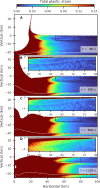
Fig. 1.
Fig. 1.. Time series of our fiducial model of the formation of an icy multiring basin.
Simulation is of a 1.5-km-radius impactor striking a 20-km-thick ice shell with a 6-km-thick conductive lid. Material is colored according to total plastic strain. White dashed curves indicate the material boundaries (i.e., ice shell and ocean). The insets are a magnified view of the upper 6 km of the conductive ice lid and outer portions of the basin where graben would form. Figure S1 shows the total plastic strain in log scale, and fig. S4 outlines the location of graben at 600 s. Movie S1 is an animation of this figure. (A) shows the formation of the transient crater, (B) shows the formation of the central uplift, (C) shows the formation of faults, and (D) represents the enhancement of faults during a secondary phase of collapse (see the main text for details).
Fig. 2.
Fig. 2.. Effect of ice shell thickness on radial strain.
Radial strain is calculated at an initial depth of 1 km (see details in Materials and Methods). The choice of initial depth has little effect on the results (fig. S11A). (A) Radial strain from simulations with an impactor radius of 1.5 km compared to observation of Callanish. Each thick colored line depicts the results of a simulation with a different ice shell thickness (see the legend). Thin gray lines in (A) are radial strain profiles at different azimuths determined from observed fault offsets of Callanish (21, 22). Note that the 8-km ice shell only contains a conductive lid; all other simulations include a 6-km-thick conductive lid overlying convecting ice. Shaded region in (B) represents regions of compression and thrust faulting.
Fig. 3.
Fig. 3.. Effect of conductive lid thickness and impactor radius on radial strain.
Same view as Fig. 2, but for various conductive lid thickness (lidconductive) and impactor radii (rimp) on a 20-km-thick ice shell (see the legend). (A) shows the results of simulations with a 1.5-km-radius impactor compared to observationally derived radial strain of Callanish, and (B) shows the simulation results with a 1.8-km-radius impactor compared to observationally derived radial strain of Tyre. Thin gray lines in (A) are radial strain profiles at different azimuths determined from observed fault offsets of Callanish and that in (B) for Tyre, respectively (21, 22).
Fig. 4.
Fig. 4.. Effect of impactor radius and ice shell thickness on radial strain.
Same view as Fig. 2, but for impactor radii (rimp) on the 10- to 30-km ice shell case. (A) shows simulation results with a 10-km-thick ice shell, (B) 20-km-thick ice shell, and (C) of 30-km-thick ice shell. Thin gray lines are radial strain profiles at different azimuths determined from observed fault offsets of Callanish (21, 22). All simulations assume a 6-km-thick conductive lid overlying convecting ice.

References

    1. Khurana K. K., Kivelson M. G., Stevenson D. J., Schubert G., Russell C. T., Walker R. J., Polanskey C., Induced magnetic fields as evidence for subsurface oceans in Europa and Callisto. Nature 395, 777–780 (1998). - PubMed
    1. Kivelson M. G., Khurana K. K., Russell C. T., Volwerk M., Walker R. J., Zimmer C., Galileo magnetometer measurements: A stronger case for a subsurface ocean at europa. Science 289, 1340–1343 (2000). - PubMed
    1. Hoppa G. V., Tufts B. R., Greenberg R., Geissler P. E., Formation of cycloidal features on europa. Science 285, 1899–1902 (1999). - PubMed
    1. Greenberg R., Geissler P., Tufts B. R., Hoppa G. V., Habitability of Europa’s crust: The role of tidal-tectonic processes. J. Geophys. Res. Planets 105, 17551–17562 (2000).
    1. O’Brien D. P., Geissler P., Greenberg R., A melt-through model for chaos formation on Europa. Icarus 156, 152–161 (2002).