. 2024 Jul;13(17):e2304028.
doi: 10.1002/adhm.202304028. Epub 2024 Apr 3.

High-Scale 3D-Bioprinting Platform for the Automated Production of Vascularized Organs-on-a-Chip

Affiliations

High-Scale 3D-Bioprinting Platform for the Automated Production of Vascularized Organs-on-a-Chip

Anna Fritschen et al. Adv Healthc Mater. 2024 Jul.

Abstract

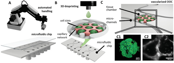
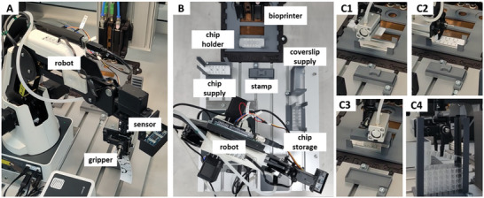
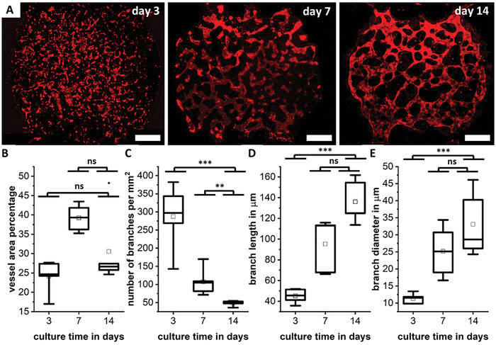
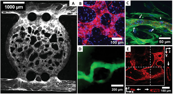
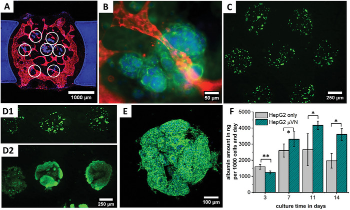
3D bioprinting possesses the potential to revolutionize contemporary methodologies for fabricating tissue models employed in pharmaceutical research and experimental investigations. This is enhanced by combining bioprinting with advanced organs-on-a-chip (OOCs), which includes a complex arrangement of multiple cell types representing organ-specific cells, connective tissue, and vasculature. However, both OOCs and bioprinting so far demand a high degree of manual intervention, thereby impeding efficiency and inhibiting scalability to meet technological requirements. Through the combination of drop-on-demand bioprinting with robotic handling of microfluidic chips, a print procedure is achieved that is proficient in managing three distinct tissue models on a chip within only a minute, as well as capable of consecutively processing numerous OOCs without manual intervention. This process rests upon the development of a post-printing sealable microfluidic chip, that is compatible with different types of 3D-bioprinters and easily connected to a perfusion system. The capabilities of the automized bioprint process are showcased through the creation of a multicellular and vascularized liver carcinoma model on the chip. The process achieves full vascularization and stable microvascular network formation over 14 days of culture time, with pronounced spheroidal cell growth and albumin secretion of HepG2 serving as a representative cell model.

Keywords: bioprinting; organ‐on‐a‐chip; robotics; vascularization.


Conflict of interest statement

The authors declare no conflict of interest.

Figures

Figure 1
Figure 1
Sketch of the process steps toward an automized fabrication process of vascularized OOCs. A robotic system automatically handles custom‐designed microfluidic chips (A) in the pre‐ and post‐process of 3D‐bioprinting (B). Inside the tissue chamber of the microfluidic chip, printed islets of HepG2 cells proliferate and form agglomerates, with a microvascular network forming during culture time (C).
Figure 2
Figure 2
Transparent microfluidic chip prototypes were printed using an adapted 3D‐DLP print process. The printed chips offer a wide opening for the print head over the central chamber (A) that is closed with a plug after the bioprinting process (B,C). After testing different chip geometries, the final design contains a 3 mm wide tissue chamber with two round pillars separating the chamber from the channels (D). The COP custom‐fabricated chips offer three OOC units on a standard microscopy slide format accessible via Luer connectors. The bottom of the chip is covered by a double‐sided cytocompatible tape, which is sealed by a protective foil (E). After the bioprint process, the protective foil is removed and the chip is sealed with a polymer coverslip (F). The surface energy (G) and contact angle to a bioprinted agarose hydrogel (H) show no significant (ns) difference between both substrate materials, though the roughness is smaller for the DLP‐printed surface with *** for p < 0.001 (I).
Figure 3
Figure 3
Shear viscosity measurements show Newton‐like flow behavior for agarose and strong shear thinning for fibrinogen (A). Drop volumes of both bioinks (B) as measured in flight (C). The very low nozzle shear stresses of below 1 kPa that cells experience during printing (D) do not significantly (ns) affect the metabolic activity of HUVEC (E) or the cell viability 14 h post‐printing of HDF cells (F) with live cells stained with FDA (green) and dead cells stained with PI (red). Scale bar showing 500 µm. The average drop diameter is around 850 µm on both DLP printed prototypes and the final chip out of COP with no significant difference between the substrate (ns) (G). The resulting drop height is around 140 µm on COP as imaged from the side with a scale bar showing 300 µm (H).
Figure 4
Figure 4
Overview of the printing configuration. The parenchymal bioink containing HepG2 is placed in a heated print head to keep the agarose liquid, while the vasculogenesis bioink is in a cooled print head to prevent fibrinogenesis. The chip is placed on a temperature‐controlled sample holder (A) that ensures repeatable positioning of the chips inside the printer (B). First, seven individual drops of the parenchymal bioink (red) are printed and cooled (C), before the chamber is filled with the vasculogenesis bioink (stained in green for better visualization) and the chip sealed (D).
Figure 5
Figure 5
Images of the robotic transport and manipulation system. The commercial robot is equipped with an ultrasonic sensor, as well as a printed gripper (A). The full system comprises a robot, supply points for microfluidic chips and coverslips, a temperature‐controlled chip holder for bioprinting, and a stamp for sealing, as well as a storage point for finished chips (B). Steps along the process chain include chip delivery (C1), protective foil removal (C2), sealing (C3), and chip storage (C4).
Figure 6
Figure 6
On‐chip culture of the fibrin bioink results in the formation and maturation of fine, self‐assembled microvascular networks over the course of 14 days, with CD‐31 stained red (A). Scale bar showing 500 µm. The vessel area percentage per chip (B), the branch density (C), the branch length (D), and the branch diameter (E) are given. Differences between days are marked as ns for not significant, ** for p < 0.01, *** for p < 0.001.
Figure 7
Figure 7
On‐chip culture of the fibrin bioink results in a fine, µVN by HUVEC throughout the whole chip after 14 days of culture (A), staining of CD‐31 (white). The network is highly branched with various diameters (B) and HDF lining the outer vessel walls as indicated by white arrows (C) as seen in confocal microscopy with CD‐31 (red), nuclei (blue), and actin filaments (green) stained. The networks can be perfused by 70 kDa FITC‐dextran (D) and show an open lumen (indicated by white arrows) as visible in a z‐projection image with slice direction shown in x‐ and y‐plane as indicated by white lines (E) with CD‐31stained red.
Figure 8
Figure 8
In the tri‐culture, HepG2 islands (white circles) are surrounded by the vascular network (A,B). After printing HepG2 cells (C), they proliferate strongly between day 0 (D1) and 14 (D2), forming spheroidal agglomerations inside the agarose matrix with no intent of growing outside (E). Albumin synthesis increases during the first 11 days and is higher when the model is supported by a µVN (F), with * for p < 0.05 and ** for p < 0.01.

References

    1. Moutinho S., Nat. Med. 2023, 29, 2151. - PubMed
    1. Ewart L., Apostolou A., Briggs S. A., Carman C. V., Chaff J. T., Heng A. R., Jadalannagari S., Janardhanan J., Jang K., Joshipura S. R., Kadam M. M., Kanellias M., Kujala V. J., Kulkarni G., Le C. Y., Lucchesi C., Manatakis D. V., Maniar K. K., Quinn M. E., Ravan J. S., Rizos A. C., Sauld J. F. K., Sliz J. D., Tien‐street W., Trinidad D. R., Velez J., Wendell M., Irrechukwu O., Mahalingaiah P. K., Ingber D. E., et al., Nat Commun 2022, 2, 154. - PMC - PubMed
    1. Herland A., Maoz B. M., Das D., Somayaji M. R., Prantil‐Baun R., Novak R., Cronce M., Huffstater T., Jeanty S., Ingram M., Chalkiadaki A., Chou D. B., Marquez S., Delahanty A., Jalili‐Firoozinezhad S., Milton Y., Sontheimer‐Phelps A., Swenor B., Levy O., Parker K. K., Przekwas A., Ingber D. E., Nat. Biomed. Eng. 2020, 4, 421. - PMC - PubMed
    1. Ingber D. E., Nat. Rev. 2022, 23, 467. - PMC - PubMed
    1. Fritschen A., Blaeser A., Biomaterials 2020, 268, 120556. - PubMed

LinkOut - more resources