. 2024 Mar 25;11(2):024302.
doi: 10.1063/4.0000240. eCollection 2024 Mar.

High energy electron diffraction instrument with tunable camera length

Affiliations

High energy electron diffraction instrument with tunable camera length

P Denham et al. Struct Dyn. .

Abstract

Ultrafast electron diffraction (UED) stands as a powerful technique for real-time observation of structural dynamics at the atomic level. In recent years, the use of MeV electrons from radio frequency guns has been widely adopted to take advantage of the relativistic suppression of the space charge effects that otherwise limit the temporal resolution of the technique. Nevertheless, there is not a clear choice for the optimal energy for a UED instrument. Scaling to beam energies higher than a few MeV does pose significant technical challenges, mainly related to the inherent increase in diffraction camera length associated with the smaller Bragg angles. In this study, we report a solution by using a compact post-sample magnetic optical system to magnify the diffraction pattern from a crystal Au sample illuminated by an 8.2 MeV electron beam. Our method employs, as one of the lenses of the optical system, a triplet of compact, high field gradients (>500 T/m), small-gap (3.5 mm) Halbach permanent magnet quadrupoles. Shifting the relative position of the quadrupoles, we demonstrate tuning the magnification by more than a factor of two, a 6× improvement in camera length, and reciprocal space resolution better than 0.1 Å-1 in agreement with beam transport simulations.


Conflict of interest statement

The authors have no conflicts to disclose.

Figures

FIG. 1.
FIG. 1.
Ray diagram showing an angular magnification telescope. Initially, parallel rays converge to the same position at the detector with a magnified offset compared to the objective's back focal plane.
FIG. 2.
FIG. 2.
Cartoon depicting the angular magnification telescope concept implemented using two quadrupole triplets as applied to the Pegasus UED beamline.
FIG. 3.
FIG. 3.
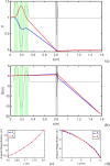
(a) The cosine-like principal ray is depicted traversing an optimized optics setup where the green quadrupole triplet positions back focal planes just in front of the PMQ triplet. The PMQ triplet then forms images on the downstream detector at z=1.6m. (b) The sine-like principal ray is magnified at the detector. (c) An optimization scan for angular magnification is conducted for a nearby screen, with symmetric back focal planes set at varied positions while the PMQ triplet maintains imaging at z=1.02m. (d) Back focal planes are separated using the green quadrupole triplet, and the spacings of the PMQ triplet are optimized to restore symmetric imaging at z=1.02m.
FIG. 4.
FIG. 4.
(a) Technical drawing of the PMQs as mounted on the flexure stage. (b) Setup of the pulsed-wire alignment technique.
FIG. 5.
FIG. 5.
(a) Calibration of oscilloscope signal of central peak with the PMQs' displacement. (b) Oscilloscope signal of the central peak when the first and third PMQs are moved. (c) Signal with different transverse offset. The bottom axis is the signal timing, and the top axis is the corresponding distance. (d) Retrieved PMQ field from pulsed-wire signal.
FIG. 6.
FIG. 6.
Pegasus beamline technical drawings showing the main elements in the experimental setup.
FIG. 7.
FIG. 7.
Results from self-consistent start-to-end GPT simulation of the Pegasus beamline including RF gun, linac and space charge effects. The rms horizontal (blue solid) and vertical (dashed) envelopes and the kinetic energy (red) are shown up to the detector.
FIG. 8.
FIG. 8.
Single-shot diffraction patterns captured at the z = 1.02 m fluorescent screen. For (a) the linac is turned off and the kinetic energy is 3.1 MeV. The green quadrupole triplet is tuned to focus on the detector. (b)–(d) are acquired with the linac turned on and the beam energy at 8.2 MeV, (b) is obtained without focusing, (c) with focusing, and (d) with magnification.
FIG. 9.
FIG. 9.
A comparison of integrated cross sections for Au in the range 0.01–100 MeV. The red curve shows the total cross section, and the blue and green curves are integrated up to first and second Bragg orders, respectively. In black is an integration over forward-directed angles limited to 1 mrad.
FIG. 10.
FIG. 10.
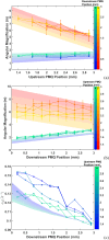
Scan results where spacing of (a) upstream PMQ spacing and (b) downstream PMQ spacing is decreased from 3 mm. (c) Horizontal Q-resolution during the scan.
FIG. 11.
FIG. 11.
(a) Quadrupole and octupole Fourier components and their axial dependence are shown for the 3 and 6 mm PMQs. (b) Overlay of horizontally steered diffraction beamlet centroid positions, as measured on the detector, with a 3rd-order aberrated image of an initially square grid of rays. The initial positions of the square grid fill the expected region of the first-order Bragg peaks at the objective back focal plane.

References

    1. Zewail A. H., “ 4D ultrafast electron diffraction, crystallography, and microscopy,” Annu. Rev. Phys. Chem. 57, 65–103 (2006).10.1146/annurev.physchem.57.032905.104748 - DOI - PubMed
    1. Sciaini G. and Miller R. D., “ Femtosecond electron diffraction: Heralding the era of atomically resolved dynamics,” Rep. Prog. Phys. 74, 096101 (2011).10.1088/0034-4885/74/9/096101 - DOI
    1. Filippetto D., Musumeci P., Li R. K., Siwick B. J., Otto M. R., Centurion M., and Nunes J. P. F., “ Ultrafast electron diffraction: Visualizing dynamic states of matter,” Rev. Mod. Phys. 94, 045004 (2022).10.1103/RevModPhys.94.045004 - DOI
    1. Yang J., Zhu X., Wolf T. J., Li Z., Nunes J. P. F., Coffee R., Cryan J. P., Gühr M., Hegazy K., Heinz T. F. et al., “ Imaging CF3I conical intersection and photodissociation dynamics with ultrafast electron diffraction,” Science 361, 64–67 (2018).10.1126/science.aat0049 - DOI - PubMed
    1. Carbone F., Baum P., Rudolf P., and Zewail A. H., “ Structural preablation dynamics of graphite observed by ultrafast electron crystallography,” Phys. Rev. Lett. 100, 035501 (2008).10.1103/PhysRevLett.100.035501 - DOI - PubMed