

Surface Roughness of Interior Fine Flow Channels in Selective Laser Melted Ti-6Al-4V Alloy Components
- PMID: 38542595
- PMCID: PMC10972332
- DOI: 10.3390/mi15030348
Surface Roughness of Interior Fine Flow Channels in Selective Laser Melted Ti-6Al-4V Alloy Components
Abstract
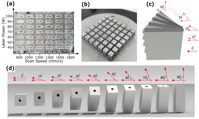
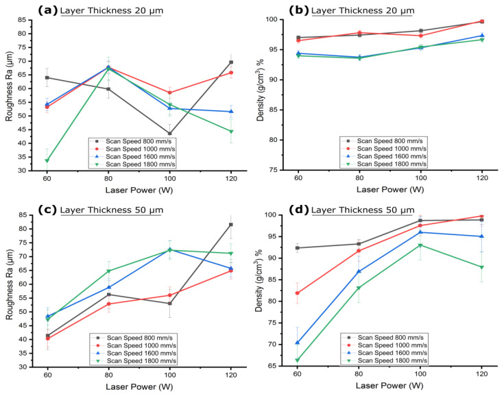
A challenge remains in achieving adequate surface roughness of SLM fabricated interior channels, which is crucial for fuel delivery in the space industry. This study investigated the surface roughness of interior fine flow channels (1 mm diameter) embedded in SLM fabricated TC4 alloy space components. A machine learning approach identified layer thickness as a significant factor affecting interior channel surface roughness, with an importance score of 1.184, followed by scan speed and laser power with scores of 0.758 and 0.512, respectively. The roughness resulted from thin layer thickness of 20 µm, predominantly formed through powder adherence, while from thicker layer of 50 µm, the roughness was mainly due to the stair step effect. Slow scan speeds increased melt pools solidification time at roof overhangs, causing molten metal to sag under gravity. Higher laser power increased melt pools temperature and led to dross formation at roof overhangs. Smaller hatch spaces increased roughness due to overlapping of melt tracks, while larger hatch spaces reduced surface roughness but led to decreased part density. The surface roughness was recorded at 34 µm for roof areas and 26.15 µm for floor areas. These findings contribute to potential adoption of TC4 alloy components in the space industry.
Keywords: additive manufacturing; build orientation; confined geometry; heat penetration; interior channel; laser powder bed fusion; overhang; process parameters optimization; space industry; trapped powder.
Conflict of interest statement
The authors declare no conflicts of interest.
Figures


Similar articles
-
Effects of Process Parameters and Process Defects on the Flexural Fatigue Life of Ti-6Al-4V Fabricated by Laser Powder Bed Fusion.Materials (Basel). 2024 Sep 16;17(18):4548. doi: 10.3390/ma17184548. Materials (Basel). 2024. PMID: 39336289 Free PMC article.
-
Pandora's Box-Influence of Contour Parameters on Roughness and Subsurface Residual Stresses in Laser Powder Bed Fusion of Ti-6Al-4V.Materials (Basel). 2020 Jul 28;13(15):3348. doi: 10.3390/ma13153348. Materials (Basel). 2020. PMID: 32731434 Free PMC article.
-
Densification, Tailored Microstructure, and Mechanical Properties of Selective Laser Melted Ti-6Al-4V Alloy via Annealing Heat Treatment.Micromachines (Basel). 2022 Feb 19;13(2):331. doi: 10.3390/mi13020331. Micromachines (Basel). 2022. PMID: 35208455 Free PMC article.
-
Numerical Study to Analyze the Influence of Process Parameters on Temperature and Stress Field in Powder Bed Fusion of Ti-6Al-4V.Materials (Basel). 2025 Jan 15;18(2):368. doi: 10.3390/ma18020368. Materials (Basel). 2025. PMID: 39859839 Free PMC article.
-
Analysis of the mechanical and physicochemical properties of Ti-6Al-4 V discs obtained by selective laser melting and subtractive manufacturing method.J Biomed Mater Res B Appl Biomater. 2021 Mar;109(3):420-427. doi: 10.1002/jbm.b.34710. Epub 2020 Aug 20. J Biomed Mater Res B Appl Biomater. 2021. PMID: 32815312 Review.
Cited by
-
Graining and Texturing of Metal Surfaces by Picosecond Laser Treatment.Materials (Basel). 2025 Mar 21;18(7):1398. doi: 10.3390/ma18071398. Materials (Basel). 2025. PMID: 40271567 Free PMC article.
-
Investigation of Distortion, Porosity and Residual Stresses in Internal Channels Fabricated in Maraging 300 Steel by Laser Powder Bed Fusion.Materials (Basel). 2025 Feb 25;18(5):1019. doi: 10.3390/ma18051019. Materials (Basel). 2025. PMID: 40077244 Free PMC article.
References
-
- Madhavadas V., Srivastava D., Chadha U., Aravind Raj S., Sultan M.T.H., Shahar F.S., Shah A.U.M. A Review on Metal Additive Manufacturing for Intricately Shaped Aerospace Components. CIRP J. Manuf. Sci. Technol. 2022;39:18–36. doi: 10.1016/j.cirpj.2022.07.005. - DOI
-
- Balaji D., Ranga J., Bhuvaneswari V., Arulmurugan B., Rajeshkumar L., Manimohan M.P., Devi G.R., Ramya G., Masi C. Additive Manufacturing for Aerospace from Inception to Certification. J. Nanomater. 2022;2022:7226852. doi: 10.1155/2022/7226852. - DOI
-
- Xiong W., Pan R., Yan C., He M., Chen Q., Li S., Chen X., Hao L., Li Y. Subdivisional Modelling Method for Matched Metal Additive Manufacturing and Its Implementation on Novel Negative Poisson’s Ratio Lattice Structures. Addit. Manuf. 2023;68:103525. doi: 10.1016/j.addma.2023.103525. - DOI
-
- Zhang L., Li Y., Hu R., Yin J., Sun Q., Li X., Gao L., Wang H., Xiong W., Hao L. Freeform Thermal-Mechanical Bi-Functional Cu-Plated Diamond/Cu Metamaterials Manufactured by Selective Laser Melting. J. Alloys Compd. 2023;968:172010. doi: 10.1016/j.jallcom.2023.172010. - DOI
Grants and funding
- 2022YFB4602502 and 2023YFB4605603/NATIONAL KEY RESEARCH AND DEVELOPMENT PROGRAM
- 2021BEC010/SCIENCE AND TECHNOLOGY REVEAL SYSTEM PROJECT OF HUBEI PROVINCE
- 2022BAA057/KEY RESEARCH AND DEVELOPMENT PROGRAM FUND OF HUBEI PROVINCE
- 8091B042207/JOINT FUND INNOVATION TEAM PROJECT OF MINISTRY OF EDUCATION FOR EQUIPMENT PRERESEARCH
- SKLSP202325/STATE KEY LABORATORY OF SOLIDIFICATION PROCESSING IN NPU
LinkOut - more resources
Full Text Sources
