

Modified NiFe2O4-Supported Graphene Oxide for Effective Urea Electrochemical Oxidation and Water Splitting Applications
- PMID: 38542852
- PMCID: PMC10974038
- DOI: 10.3390/molecules29061215
Modified NiFe2O4-Supported Graphene Oxide for Effective Urea Electrochemical Oxidation and Water Splitting Applications
Abstract
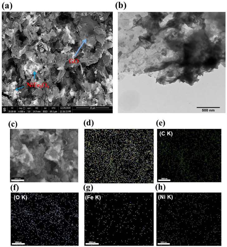
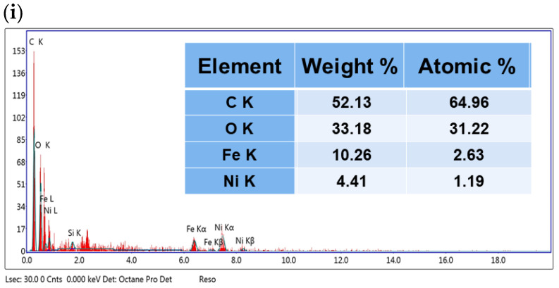
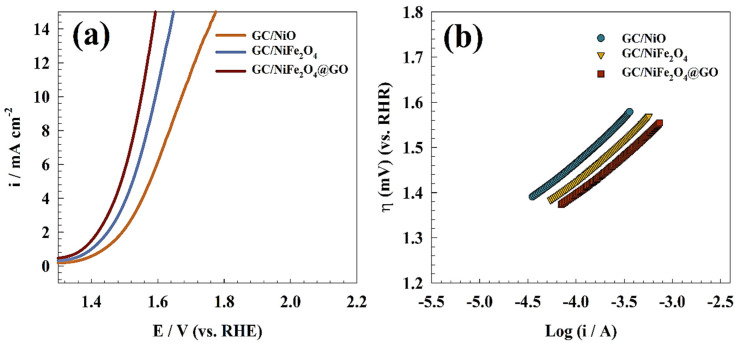
The production of green hydrogen using water electrolysis is widely regarded as one of the most promising technologies. On the other hand, the oxygen evolution reaction (OER) is thermodynamically unfavorable and needs significant overpotential to proceed at a sufficient rate. Here, we outline important structural and chemical factors that affect how well a representative nickel ferrite-modified graphene oxide electrocatalyst performs in efficient water splitting applications. The activities of the modified pristine and graphene oxide-supported nickel ferrite were thoroughly characterized in terms of their structural, morphological, and electrochemical properties. This research shows that the NiFe2O4@GO electrode has an impact on both the urea oxidation reaction (UOR) and water splitting applications. NiFe2O4@GO was observed to have a current density of 26.6 mA cm-2 in 1.0 M urea and 1.0 M KOH at a scan rate of 20 mV s-1. The Tafel slope provided for UOR was 39 mV dec-1, whereas the GC/NiFe2O4@GO electrode reached a current of 10 mA cm-2 at potentials of +1.5 and -0.21 V (vs. RHE) for the OER and hydrogen evolution reaction (HER), respectively. Furthermore, charge transfer resistances were estimated for OER and HER as 133 and 347 Ω cm2, respectively.
Keywords: fuel cells; graphene oxide; nickel ferrite; urea electrooxidation; water splitting.
Conflict of interest statement
The authors declare that there are no conflicts of interest regarding the publication of this paper.
Figures


References
-
- Singh R.K., Rajavelu K., Montag M., Schechter A. Advances in catalytic electrooxidation of urea: A review. Energy Technol. 2021;9:2100017. doi: 10.1002/ente.202100017. - DOI
-
- Sayed E.T., Eisa T., Mohamed H.O., Abdelkareem M.A., Allagui A., Alawadhi H., Chae K.-J. Direct urea fuel cells: Challenges and opportunities. J. Power Sources. 2019;417:159–175. doi: 10.1016/j.jpowsour.2018.12.024. - DOI
-
- Xu W., Wu Z., Tao S. Urea-Based Fuel Cells and Electrocatalysts for Urea Oxidation. Energy Technol. 2016;4:1329–1337. doi: 10.1002/ente.201600185. - DOI
-
- Lan R., Tao S., Irvine J.T.S. A direct urea fuel cell—Power from fertiliser and waste. Energy Environ. Sci. 2010;3:438–441. doi: 10.1039/b924786f. - DOI
-
- Ke K., Wang G., Cao D., Wang G. Electrocatalysis. Springer; Berlin/Heidelberg, Germany: 2020. Recent Advances in the Electro-Oxidation of Urea for Direct Urea Fuel Cell and Urea Electrolysis; pp. 41–78.
LinkOut - more resources
Full Text Sources
Research Materials
Miscellaneous
