. 2024 Mar 28;15(1):2741.
doi: 10.1038/s41467-024-46908-2.

Efficient excitation and control of integrated photonic circuits with virtual critical coupling

Affiliations

Efficient excitation and control of integrated photonic circuits with virtual critical coupling

Jakob Hinney et al. Nat Commun. .

Abstract

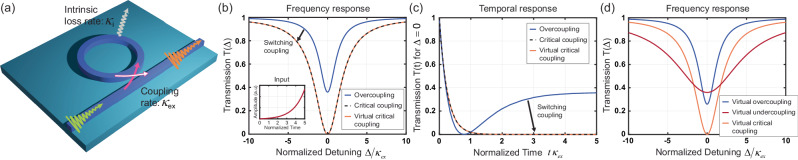
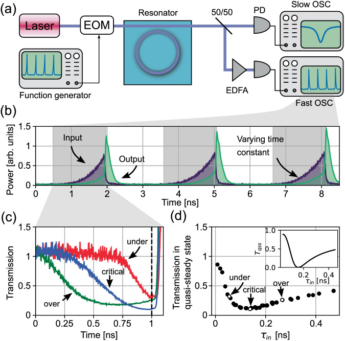
Critical coupling in integrated photonic devices enables the efficient transfer of energy from a waveguide to a resonator, a key operation for many applications. This condition is achieved when the resonator loss rate is equal to the coupling rate to the bus waveguide. Carefully matching these quantities is challenging in practice, due to variations in the resonator properties resulting from fabrication and external conditions. Here, we demonstrate that efficient energy transfer to a non-critically coupled resonator can be achieved by tailoring the excitation signal in time. We rely on excitations oscillating at complex frequencies to load an otherwise overcoupled resonator, demonstrating that a virtual critical coupling condition is achieved if the imaginary part of the complex frequency equals the mismatch between loss and coupling rate. We probe a microring resonator with tailored pulses and observe a minimum intensity transmission T = 0.11 in contrast to a continuous-wave transmission T = 0.58 , corresponding to 8 times enhancement of intracavity intensity. Our technique opens opportunities for enhancing and controlling on-demand light-matter interactions for linear and nonlinear photonic platforms.


Conflict of interest statement

The authors declare no competing interests.

Figures

Fig. 1
Fig. 1. Frequency and temporal responses of a microring resonator excited with complex frequency signals.
a Schematic of a microring resonator with intrinsic loss κi side-coupled to a bus waveguide with coupling rate κex. An impinging pulse is launched through the bus waveguide to excite the resonator, and the signal is measured at the end of the waveguide. b Transmission spectrum of an overcoupled resonator (κex>κi, blue) and quasi-steady state transmission of the same resonator excited with a tailored complex frequency pulse (inset) leading to virtual critical coupling (orange), compared to CW-transmission of a critically coupled resonator (dashed). c Temporal evolution of the transmission for overcoupled (blue), critically coupled (dashed), and virtually critically coupled (orange) scenarios excited at resonance (Δ=0). d Frequency spectrum of the transmission for virtually critically coupled (orange), virtually overcoupled (blue), and virtually undercoupled (red) scenarios. By varying the growth rate of the input signal, it is possible to control the coupling regime between resonator and waveguide.
Fig. 2
Fig. 2. Characterization of the microring resonator.
a Microscope image of the SiN integrated microresonator coupled to the bus waveguide. b Schematic of the cross-section for the 1500 nm wide × 730 nm high SiN microresonator covered with SiO2, overlaid with the FDTD-simulated mode shape of the fundamental TE optical mode in the waveguide structure. c Cavity ring-down measurement, where the measured data (green line) is fitted (dashed line) to determine the lifetime of the cavity. d Measured transmission spectrum at real frequencies of the SiN resonator. The intensity transmission dip at zero detuning (Δ=0) is 0.58. The estimated intrinsic loss and external coupling rates are κi/2π=0.16GHz and κex/2π=1.18GHz; therefore, the resonator is strongly overcoupled to the bus waveguide. e Density plot of 1/T(f) in the complex frequency plane. The pole (brightest spot), which is marked by the blue circle, provides the condition for virtual critical coupling.
Fig. 3
Fig. 3. Experimental setup and recorded transmission plots.
a Schematic of the experimental setup to control the complex frequency of excitation via an electro-optic modulator (EOM) and detect the transmitted signals with high temporal resolution through a fast oscilloscope (30 GHz), while monitoring the averaged transmission with a slow oscilloscope. PD photodetector, OSC oscilloscope, and EDFA erbium-doped fiber amplifier. b Sequence of input Iinput and output Ioutput intensities for various pulse time constants. The energy stored in the resonator during the pulse decays partly into the bus waveguide and is observed as a sharp peak once the pulse ends. c Intensity transmission T=Ioutput/Iinput for virtual undercoupling (red, τin=55ps), virtual critical coupling (blue, τin=138ps), and virtual overcoupling (green, τin=266ps). d Measured intensity relative transmission in the quasi-steady state before switching off the pulse (vertical dashed line in Fig. 3c) as a function of τin; the inset shows the theoretical value of the transmission in the quasi-steady state Tqss for the same cavity parameters.
Fig. 4
Fig. 4. Normalized stored energy η in the resonator.
Effective cavity loading is enhanced in the marked area due to virtual critical coupling. Inset: theoretical calculation for the same parameter range.
Fig. 5
Fig. 5. Illustration of input and output pulses under various excitation scenarios.
Virtual critical coupling is demonstrated at τin=138ps (left), virtual overcoupling is demonstrated at τin=266ps (middle), and virtual undercoupling is demonstrated at τin=55ps (right). a Theoretical predictions for the three cases. Inputs (purple), outputs (green), and analytical curves (red dashed) are represented. The analytical curves show that all outputs decay at the time constant of the cavity τ=119ps. b Corresponding experimental results are displayed.

References

    1. Haus, H. A. Waves and Fields in Optoelectronics, (Prentice-Hall, 1984).
    1. Yariv A. Universal relations for coupling of optical power between microresonators and dielectric waveguides. Electron. Lett. 2000;36:321. doi: 10.1049/el:20000340. - DOI
    1. Heebner JE, Vincent W, Schweinsberg A, Boyd RW, Jackson DJ. Optical transmission characteristics of fiber ring resonators. IEEE J. Quantum Electron. 2004;40:726. doi: 10.1109/JQE.2004.828232. - DOI
    1. Bogaerts W, et al. Silicon microring resonators. Laser Photonics Rev. 2012;6:47. doi: 10.1002/lpor.201100017. - DOI
    1. Thongrattanasiri S, Koppens FHL, García de Abajo FJ. Complete optical absorption in periodically patterned graphene. Phys. Rev. Lett. 2012;108:047401. doi: 10.1103/PhysRevLett.108.047401. - DOI - PubMed