Review
. 2024 Apr 30;24(9):2371-2396.
doi: 10.1039/d3lc00743j.

Direct laser writing-enabled 3D printing strategies for microfluidic applications

Affiliations
Review

Direct laser writing-enabled 3D printing strategies for microfluidic applications

Olivia M Young et al. Lab Chip. .

Erratum in

Abstract

Over the past decade, additive manufacturing-or "three-dimensional (3D) printing"-has attracted increasing attention in the Lab on a Chip community as a pathway to achieve sophisticated system architectures that are difficult or infeasible to fabricate via conventional means. One particularly promising 3D manufacturing technology is "direct laser writing (DLW)", which leverages two-photon (or multi-photon) polymerization (2PP) phenomena to enable high geometric versatility, print speeds, and precision at length scales down to the 100 nm range. Although researchers have demonstrated the potential of using DLW for microfluidic applications ranging from organ on a chip and drug delivery to micro/nanoparticle processing and soft microrobotics, such scenarios present unique challenges for DLW. Specifically, microfluidic systems typically require macro-to-micro fluidic interfaces (e.g., inlet and outlet ports) to facilitate fluidic loading, control, and retrieval operations; however, DLW-based 3D printing relies on a micron-to-submicron-sized 2PP volume element (i.e., "voxel") that is poorly suited for manufacturing these larger-scale fluidic interfaces. In this Tutorial Review, we highlight and discuss the four most prominent strategies that researchers have developed to circumvent this trade-off and realize macro-to-micro interfaces for DLW-enabled microfluidic components and systems. In addition, we consider the possibility that-with the advent of next-generation commercial DLW printers equipped with new dynamic voxel tuning, print field, and laser power capabilities-the overall utility of DLW strategies for Lab on a Chip fields may soon expand dramatically.


Conflict of interest statement

There are no conflicts to declare.

Figures

Fig. 1
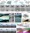
Fig. 1. Fundamental concepts and developments for “direct laser writing (DLW)”. (a) Theory of two-photon absorption. Dashed lines = behaviour of an atom; upward and downward arrows represent absorbed and emitted photons, respectively. (b) Conceptual illustration and experimental results from the first demonstration in the literature for fabricating a three-dimensional (3D) model by exposing a liquid photomaterial to UV light in a point-by-point, layer-by-layer manner. (c) Conceptual illustrations of two configurations of the “stereolithography apparatus (SLA)” for building 3D objects via point-by-point, layer-by-layer polymerization of a photomaterial. (d) Schematic of the optical system and experimental results from the first demonstration in the literature for fabricating 3D microstructures via two-photon polymerization (2PP). (e–i) Conceptual illustrations of a representative DLW manufacturing process to produce 3D “DLW” microstructures. (e) Uncured photomaterial atop a print substrate. (f) A pulsed infrared (IR) laser is scanned point by point and/or layer by layer to initiate 2PP in target locations. (g) Completion of the DLW printing process. (h) The print is immersed in a developing agent to remove any uncured photomaterial. (i) Completion of the development process results in final microstructures—still adhered to the print substrate—comprising cured (crosslinked) photomaterial.
Fig. 2
Fig. 2. Microfluidic system fabrication based on the use of DLW-printed moulds for microreplication. (a–e) Conceptual illustrations of a representative fabrication protocol. (a) Master mould with DLW-printed microchannel structures. (b) Micromoulding of a material, such as polydimethylsiloxane (PDMS). (c) Following removal of the micromoulded material from the master mould, through-holes are produced at desired locations for macro-to-micro fluidic interfaces (e.g., inlet/outlet ports). (d) The micromoulded material is enclosed using a substrate (e.g., by bonding PDMS to glass). (e) Fluid is loaded into the enclosed microfluidic channel. (f–k) Representative examples in the literature. (f) Micrographs of (top) master moulds, and (bottom) corresponding replicated PDMS cross-sectional profiles for various microchannel designs. (g) Microchannel with geometry designed to trap plant parasitic nematodes. (h) Microfluidic channels with microtopographical features for studies of cell phisicobiology. (i) Sloped microfluidic channels for applying lateral spatial shear stress gradients to cells. (j and k) Microfluidic channels designed with gradual changes in height to enhance microdroplet: (j) stability, and (k) manipulations (e.g., size-based sorting).
Fig. 3
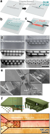
Fig. 3. Microfluidic systems fabricated by enclosing DLW-printed 3D microstructures. (a–c) Conceptual illustrations of a representative fabrication protocol. (a) Microstructures DLW-printed onto a planar (i.e., flat) substrate (e.g., glass). (b) Channel enclosure. (Left) Alignment of an unenclosed microchannel with integrated macro-to-micro fluidic interfaces (e.g., an unenclosed PDMS microchannel with inlet/outlet ports) to the microstructures; and then (right) enclosure of the microfluidic system (e.g., via PDMS-to-glass bonding). (c) Loading of fluid into the enclosed microfluidic channel comprising DLW-printed 3D microstructures. (d–f) Representative examples in the literature. (d) PDMS-on-glass microfluidic system containing an array of DLW-printed 3D microrotors. (e) DLW-printed microstructures enclosed in microfluidic channels via: (top) mechanical clamping, and (bottom) PDMS-to-glass oxygen plasma bonding. (f) Microfluidic tissue culture system with DLW-printed 3D microfluidic capillary grids enclosed by mechanical clamping. (Top) Conceptual illustrations. (Bottom) Fabrication results.
Fig. 4
Fig. 4. Microfluidic systems fabricated by DLW-printing 3D microstructures inside of an unenclosed channel and then enclosing the channel with a planar substrate. (a–c) Conceptual illustrations of an example fabrication protocol. (a) DLW-printing of microstructures directly inside of an unenclosed microchannel (e.g., wet-etched glass). (b) Channel enclosure by sealing a planar substrate (e.g., a PDMS slab) with integrated macro-to-micro fluidic interfaces atop the microchannel's open surface. (c) Loading of fluid into the enclosed microfluidic channel comprising DLW-printed 3D microstructures. (d–f) Representative examples in the literature. (d and e) Micrographs of microfluidic structures, including (d) microfilters with arbitrary pore designs and (e) multidirectional crossing manifold micromixers, which were DLW-printed inside wet-etched glass microchannels and then sealed using flat PDMS slabs. (f) A 3D micromixer that was DLW-printed inside unenclosed SU-8 photoresist-on-Si microchips and then sealed using a flat PDMS slab.
Fig. 5
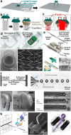
Fig. 5. Microfluidic systems fabricated by DLW-printing 3D microstructures directly inside (and fluidically sealed to the entire luminal surfaces) of enclosed microchannels—strategies referred to as “in situ DLW (isDLW)”. (a–d) Conceptual illustrations of an example fabrication protocol. (a) Enclosed microfluidic device with tapered (≥30–34°) microchannel sidewalls and integrated macro-to-micro fluidic interfaces. (b) Liquid-phase photomaterial loaded into the device. (c) Microdevice after isDLW of “DLW” microfluidic structures. (d) Loading of fluid through the complete microfluidic system (i.e., through the “DLW” microfluidic structures). (e–j) Representative examples in the literature. (e) A microfluidic spinneret isDLW-printed inside a PDMS-on-glass microfluidic system with sol–gel-coated microchannels. (f) A porous microfilter isDLW-printed inside a commercial borosilicate glass microchannel chip. (g) A micromixer with integrated filter structures isDLW-printed inside a glass microchip (produced by femtosecond laser-assisted wet etching). (h) Micrographs of (top) interweaving tubular microvessel structures, and (bottom) a microfluidic transistor (left) and fluidic barrier structure (right), which were all isDLW-printed inside microdevices composed of the thermoplastic material, cyclic olefin polymer (COP). (i) A microfluidic circuit comprising two sets of fluidic microgrippers and two distinct microfluidic transistors, which were all isDLW-printed inside of a COP–COP microdevice. (j) Micrographs (top) before, and (bottom) after isDLW-printing of microfluidic barrier structures inside of a COP–COP microdevice via a photografting approach (based on benzophenone (BP) surface modification).
Fig. 6
Fig. 6. Conceptual illustrations of a representative “oil-immersion” configuration-based DLW manufacturing process to produce 3D “DLW” microstructures. (a) Uncured photomaterial atop a thin, optically transparent print substrate with immersion oil between the underside of the print substrate and the objective lens. (b) A pulsed IR laser is scanned through the immersion oil, print substrate, and then the photomaterial (including in some case, previously polymerized microstructures) to initiate 2PP in target locations. (c) Completion of the oil-immersion mode DLW printing process.
Fig. 7
Fig. 7. Microfluidic components fabricated by DLW-printing independent 3D microfluidic entities for subsequent manual fluidic interfacing. (a–c) Conceptual illustrations of an example fabrication protocol. (a) DLW-printing of an independent microfluidic entity and removal from the print substrate. (b) Manual interfacing of the DLW-printed microfluidic entity to a mesoscale fluidic capillary, followed by the application of a sealant/adhesive. (c) Loading of fluid into (and through) the complete microfluidic component. (d–h) Representative examples in the literature. (d) DLW-printed 3D cell scaffold manually interfaced with a fluidic channel. (e) DLW-printed nuclear magnetic resonance (NMR) microfluidic component manually interfaced with mesoscale fluidic capillaries with connections fluidically sealed using epoxy. (f) DLW-printed nozzle manually interfaced with (and glued to) a glass capillary for microdroplet generation. (g) DLW-printed microfluidic structure manually interfaced (without sealants/adhesives) with a capillary bundle for delivery and sampling of nanolitre volumes. (h) DLW-printed modular gas dynamic virtual nozzle (with integrated micromixers) manually interfaced with (and glued to) glass capillaries for serial femtosecond crystallography at X-ray free-electron lasers.
Fig. 8
Fig. 8. Microfluidic components fabricated by DLW-printing 3D microfluidic structures directly atop (and fluidically sealed to) meso/macroscale fluidic couplers and systems—strategies referred to as “ex situ DLW (esDLW)”. (a–d) Conceptual illustrations of an example fabrication protocol. (a) Photomaterial deposited on the tip of a mesoscale fluidic capillary. (b and c) “DLW” microfluidic structures esDLW-printed atop the capillary (b) before, and (c) after development. (d) Loading of fluid through the complete microfluidic component (i.e., through and out of the “DLW” microfluidic structures). (e–i) Representative examples in the literature. (e and f) Micrographs of (e) micropiston-actuated microgrippers, and (f) pneumatically actuated bistable microgrippers,esDLW-printed onto glass capillaries for manipulating microspheres. (g) Microfluidic structures with arbitrary geometries esDLW-printed onto fused silica glass capillary tubes and loaded with fluid. (h) Hollow microneedle arrays esDLW-printed onto “Digital Light Processing (DLP)” 3D-printed capillaries for injecting fluid into excised mouse brains. (i) Hollow conical microneedles esDLW-printed atop a microfluidic chip with external ports (prepared by femtosecond irradiation, annealing, grinding, and polishing).
Fig. 9
Fig. 9. Fully DLW-printed microfluidic systems. (a) DLW-printed microfluidic system with one inlet and one outlet connected to 50 porous cylindrical microfluidic channels (with 1 μm array pores) for modelling the blood–brain barrier. (b) DLW-printed microfluidic system with one inlet for (i)–(iii) loading “microrobots” (i.e., magnetic liquid–core–shell particles) for drug delivery applications. (c) DLW-printed microfluidic system with two inlets for culturing cell spheroids as well as mouse cumulus–oocyte-complexes and embryos.
Fig. 10
Fig. 10. Conceptual illustrations of distinct DLW fabrication processes—based on using either a (a) fixed or (b and c) variable 2PP volume element (i.e., “voxel”)—for a demonstrative “UMD” microstructure with an internal microchannel. (a) Fixed-voxel DLW. (b) “Adaptive resolution printing” DLW, which involves adjusting the voxel shape laterally, but not vertically, over the course of a DLW print run. (c) “Voxel tuning” DLW, which involves adjusting the voxel size dynamically (i.e., scaled laterally and vertically) over the course of a DLW print run. Clocks denote example trends for elapsed print time corresponding to each process.
Fig. 11
Fig. 11. Conceptual illustrations of a representative “vat” configuration-based DLW manufacturing process to produce 3D “DLW” microstructures. (a) Uncured photomaterial inside a vat with a print substrate (in an inverted orientation) with its surface immersed in the photomaterial with an air objective lens positioned below the base of the vat. (b) A pulsed IR laser is scanned through the vat and then the photomaterial to initiate 2PP in target locations while the print substrate is raised up from the vat (layer by layer). (c) Completion of the vat DLW printing process.

References

    1. Göppert-Mayer M. Über Elementarakte mit zwei Quantensprüngen. Ann. Phys. 1931;401:273–294. doi: 10.1002/andp.19314010303. - DOI
    1. Göppert-Mayer M. Elementary processes with two quantum transitions. Ann. Phys. 2009;521:466–479. doi: 10.1002/andp.200952107-804. - DOI
    1. Maiman T. H., Ruby Laser Systems, U.S. Pat., 3353115, 1960
    1. Kaiser W. Garrett C. G. B. Two-Photon Excitation in CaF2: Eu2+ Phys. Rev. Lett. 1961;7:229–231. doi: 10.1103/PhysRevLett.7.229. - DOI
    1. Denk W. Strickler J. H. Webb W. W. Two-Photon Laser Scanning Fluorescence Microscopy. Science. 1990;248:73–76. doi: 10.1126/science.2321027. - DOI - PubMed