. 2024 Apr 9;15(1):3072.
doi: 10.1038/s41467-024-47411-4.

A 2D chiral microcavity based on apparent circular dichroism

Affiliations

A 2D chiral microcavity based on apparent circular dichroism

Tzu-Ling Chen et al. Nat Commun. .

Abstract

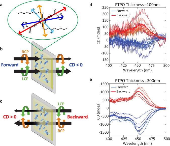
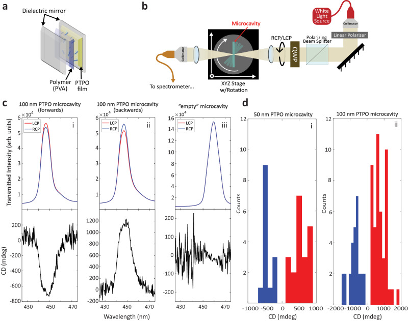
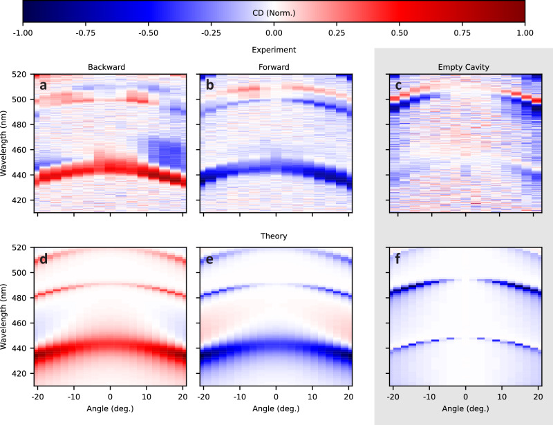
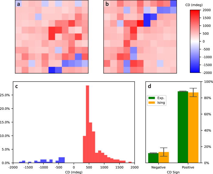
Engineering asymmetric transmission between left-handed and right-handed circularly polarized light in planar Fabry-Pérot (FP) microcavities would enable a variety of chiral light-matter phenomena, with applications in spintronics, polaritonics, and chiral lasing. Such symmetry breaking, however, generally requires Faraday rotators or nanofabricated polarization-preserving mirrors. We present a simple solution requiring no nanofabrication to induce asymmetric transmission in FP microcavities, preserving low mode volumes by embedding organic thin films exhibiting apparent circular dichroism (ACD); an optical phenomenon based on 2D chirality. Importantly, ACD interactions are opposite for counter-propagating light. Consequently, we demonstrated asymmetric transmission of cavity modes over an order of magnitude larger than that of the isolated thin film. Through circular dichroism spectroscopy, Mueller matrix ellipsometry, and simulation using theoretical scattering matrix methods, we characterize the spatial, spectral, and angular chiroptical responses of this 2D chiral microcavity.


Conflict of interest statement

The authors declare no competing interests.

Figures

Fig. 1
Fig. 1. Chiroptical properties and signal inversion of ACD-exhibiting PTPO films.
a Structure of PTPO with sketch of four largest electronic transition dipoles used in modeling colored. Asymmetric transmission properties of a 2D chiral thin film in the (b) forward geometry of a PTPO film demonstrating increased transmission of LCP light over RCP light, and in a (c) backward geometry where the sign of the CD signal is reversed. Chiroptical properties of a 100 nm (d) and 300 nm (e) PTPO film on an HR substrate measured at different spatial locations. Blue curves are acquired in the forward geometry (see b) and red curves are acquired in the backward geometry. The thick solid curves show the average from several different spots in the backward or forward direction.
Fig. 2
Fig. 2. 2D Chiral microcavity configuration and demonstration of microcavity chiroptical response.
a A schematic illustration of the FP microcavity architecture used in our experiments. b A single-beam white light system that directs the cavity transmission signal to a spectrometer. The quarter-wave plate (QWP) generates RCP and LCP. A rotational stage is employed to provide angular dispersion of the microcavity spectrum. c Transmitted intensities of RCP (red) and LCP (blue), on top, and calculated CD in mdeg (black) for the same spectral regions. (i, ii) are the same approximate spot in the same PTPO microcavity irradiated from opposite directions, while (iii) is a microcavity with no PTPO. d Maximum CD values measured over the resonant wavelength range of 400–500 nm for a variety of microcavities and microcavity positions for (i) 50 nm thick PTPO films and (ii) 100 nm thick PTPO films.
Fig. 3
Fig. 3. Angular and wavelength-dependent response of CD (normalized) for microcavity containing 100 nm PTPO.
a, b Experimental results for forward and backward propagation and contrasted (c) empty cavity signals. d, e Theoretical SMM results for forward and backward propagation alongside (f) an empty cavity, see SI for details. Signals normalized to region of maximum magnitude of CD, which is roughly equivalent for forward and backward propagation but moderately weaker in the empty cavity.
Fig. 4
Fig. 4. Spatial distribution of CD for microcavity containing PTPO 100 nm thin films.
a, b Spatial maps of CD with step size of 0.5 mm for two non-neighboring regions of PTPO. c Histogram of CD for spatial maps depicted above (a, b). d Distribution of positive and negative CD sign and standard deviations from (c) compared with that for a Metropolis-Hastings simulation of an Ising model of two domain orientations. For the Ising model, CD sign given by averaging over 100 trajectories where the substrate affinity per domain area of one orientation is 16 eV mm−2 and the interdomain coupling per shared edge length is 10 eV mm−1 (details in SI).

References

    1. Brandt JR, Salerno F, Fuchter MJ. The added value of small-molecule chirality in technological applications. Nat. Rev. Chem. 2017;1:0045. doi: 10.1038/s41570-017-0045. - DOI
    1. Huang Y, et al. Room-temperature electron spin polarization exceeding 90% in an opto-spintronic semiconductor nanostructure via remote spin filtering. Nat. Photonics. 2021;15:475–482. doi: 10.1038/s41566-021-00786-y. - DOI
    1. Mondal PC, et al. Chiral conductive polymers as spin filters. Adv. Mater. 2015;27:1924–1927. doi: 10.1002/adma.201405249. - DOI - PubMed
    1. Yoo S, Park Q-H. Chiral light–matter interaction in optical resonators. Phys. Rev. Lett. 2015;114:203003. doi: 10.1103/PhysRevLett.114.203003. - DOI - PubMed
    1. Naaman R, Paltiel Y, Waldeck DH. Chiral induced spin selectivity gives a new twist on spin-control in chemistry. Acc. Chem. Res. 2020;53:2659–2667. doi: 10.1021/acs.accounts.0c00485. - DOI - PMC - PubMed