Review
. 2024 Apr;6(2):e240020.
doi: 10.1148/ryct.240020.

Radiology: Cardiothoracic Imaging Highlights 2023

Affiliations
Review

Radiology: Cardiothoracic Imaging Highlights 2023

Gilberto J Aquino et al. Radiol Cardiothorac Imaging. 2024 Apr.

Abstract

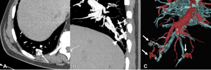
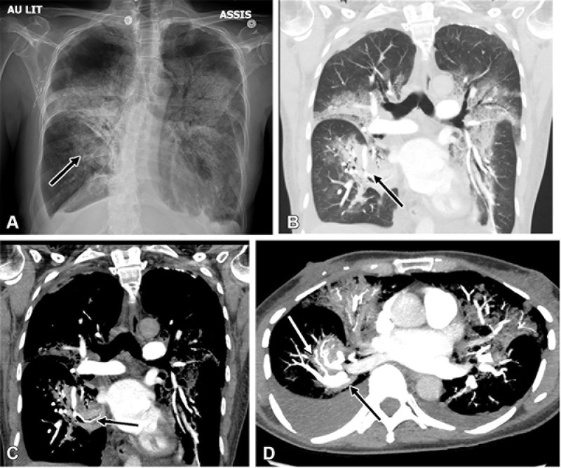
Radiology: Cardiothoracic Imaging publishes novel research and technical developments in cardiac, thoracic, and vascular imaging. The journal published many innovative studies during 2023 and achieved an impact factor for the first time since its inaugural issue in 2019, with an impact factor of 7.0. The current review article, led by the Radiology: Cardiothoracic Imaging trainee editorial board, highlights the most impactful articles published in the journal between November 2022 and October 2023. The review encompasses various aspects of coronary CT, photon-counting detector CT, PET/MRI, cardiac MRI, congenital heart disease, vascular imaging, thoracic imaging, artificial intelligence, and health services research. Key highlights include the potential for photon-counting detector CT to reduce contrast media volumes, utility of combined PET/MRI in the evaluation of cardiac sarcoidosis, the prognostic value of left atrial late gadolinium enhancement at MRI in predicting incident atrial fibrillation, the utility of an artificial intelligence tool to optimize detection of incidental pulmonary embolism, and standardization of medical terminology for cardiac CT. Ongoing research and future directions include evaluation of novel PET tracers for assessment of myocardial fibrosis, deployment of AI tools in clinical cardiovascular imaging workflows, and growing awareness of the need to improve environmental sustainability in imaging. Keywords: Coronary CT, Photon-counting Detector CT, PET/MRI, Cardiac MRI, Congenital Heart Disease, Vascular Imaging, Thoracic Imaging, Artificial Intelligence, Health Services Research © RSNA, 2024.

Keywords: Artificial Intelligence; Cardiac MRI; Congenital Heart Disease; Coronary CT; Health Services Research; PET/MRI; Photon-counting Detector CT; Thoracic Imaging; Vascular Imaging.


Conflict of interest statement

Disclosures of conflicts of interest: G.J.A. Radiology: Cardiothoracic Imaging trainee editorial board member. D.M. Radiology: Cardiothoracic Imaging trainee deputy editor for Images in Cardiothoracic Imaging; consulting fees from Segmed; stock options in Segmed. S. Alabed Radiology: Cardiothoracic Imaging trainee deputy editor for Images in Cardiothoracic Imaging; previous grants from the British Heart Foundation, The Wellcome Trust, and the Royal College of Radiologists. S. Abohashem Radiology: Cardiothoracic Imaging trainee editorial board member. L.W. Radiology: Cardiothoracic Imaging trainee editorial member. R.R.G. Radiology: Cardiothoracic Imaging associate editor and trainee editorial board mentor. D.M.E.B. Radiology: Cardiothoracic Imaging associate editor and trainee editorial board mentor. S. Abbara Editor of Radiology: Cardiothoracic Imaging; textbook author royalties from Elsevier; member of the board of directors of the Society of Cardiovascular Computed Tomography; RSNA editor-in-chief stipend to employer. K.H. Associate editor for Radiology and Radiology: Cardiothoracic Imaging.

Figures

Images show an example of low-attenuation plaques (LAPs) with multiple
near-infrared spectroscopy intravascular US–derived high-risk features.
(A) On curved planar reformatted coronary CT angiograms, the left circumflex
coronary artery is subtotally occluded with a large mixed plaque. Image on the
right with color-coded overlays shows the automated segmentation of the LAP
(orange region). (B) Enlarged three-dimensional view shows large LAP clusters.
(C) Near-infrared spectroscopy chemogram shows the plaque as lipid-rich, with a
high maximum lipid core burden index at 4-mm segment (maxLCBI4 mm) value of 880.
(D) Grayscale intravascular US cross-sectional view demonstrates extensive echo
attenuation (arrows) and an echolucent zone (arrowhead). (Reprinted, with
permission, from reference 5.)
Figure 1:
Images show an example of low-attenuation plaques (LAPs) with multiple near-infrared spectroscopy intravascular US–derived high-risk features. (A) On curved planar reformatted coronary CT angiograms, the left circumflex coronary artery is subtotally occluded with a large mixed plaque. Image on the right with color-coded overlays shows the automated segmentation of the LAP (orange region). (B) Enlarged three-dimensional view shows large LAP clusters. (C) Near-infrared spectroscopy chemogram shows the plaque as lipid-rich, with a high maximum lipid core burden index at 4-mm segment (maxLCBI4 mm) value of 880. (D) Grayscale intravascular US cross-sectional view demonstrates extensive echo attenuation (arrows) and an echolucent zone (arrowhead). (Reprinted, with permission, from reference .)
Comparison of image quality between EID CT with standard contrast media
protocol and PCD CT with low-volume contrast media protocol using a matched
radiation dose. Transverse and three-dimensional cinematic rendered images from
thoracoabdominal CTA in a 71-year-old woman in group 2 are shown. Group 2 was
used to find whether a 25% reduction in contrast media dose at the optimal
kiloelectron voltage led to noninferior image quality versus EID CT.
(A–C) Images from third-generation EID CT with automated tube voltage
selection of 90 kVp. BMI, effective diameter, CTDIvol, and SSDE were 23.7 kg/m2,
278 mm, 3.98 mGy, and 5.25 mGy, respectively; 70 mL of contrast media was used.
(D–F) Images from PCD CT with reduced contrast media volume of 52.5 mL
and VMI at 50 keV. Time interval between scans was 6 months. Mean BMI, effective
diameter, CTDIvol, and SSDE at the time of the second scan were 24.2 kg/m2, 282
mm, 3.99 mGy, and 5.27 mGy, respectively. Mean contrast-to-noise ratio for EID
CT and PCD CT were 17.2 and 17.9, respectively. BMI = body mass index, CTA = CT
angiography, CTDIvol = volumetric CT dose index, EID = energy-integrating
detector, PCD = photon-counting detector, SSDE = size-specific dose estimate,
VMI = virtual monoenergetic images. (Reprinted, with permission, from reference
9.)
Figure 2:
Comparison of image quality between EID CT with standard contrast media protocol and PCD CT with low-volume contrast media protocol using a matched radiation dose. Transverse and three-dimensional cinematic rendered images from thoracoabdominal CTA in a 71-year-old woman in group 2 are shown. Group 2 was used to find whether a 25% reduction in contrast media dose at the optimal kiloelectron voltage led to noninferior image quality versus EID CT. (A–C) Images from third-generation EID CT with automated tube voltage selection of 90 kVp. BMI, effective diameter, CTDIvol, and SSDE were 23.7 kg/m2, 278 mm, 3.98 mGy, and 5.25 mGy, respectively; 70 mL of contrast media was used. (D–F) Images from PCD CT with reduced contrast media volume of 52.5 mL and VMI at 50 keV. Time interval between scans was 6 months. Mean BMI, effective diameter, CTDIvol, and SSDE at the time of the second scan were 24.2 kg/m2, 282 mm, 3.99 mGy, and 5.27 mGy, respectively. Mean contrast-to-noise ratio for EID CT and PCD CT were 17.2 and 17.9, respectively. BMI = body mass index, CTA = CT angiography, CTDIvol = volumetric CT dose index, EID = energy-integrating detector, PCD = photon-counting detector, SSDE = size-specific dose estimate, VMI = virtual monoenergetic images. (Reprinted, with permission, from reference .)
(A) Transcatheter heart valves scanned ex vivo in ultra-high-resolution
(UHR) mode with photon-counting detector CT (PCD CT). Four different ex vivo
transcatheter heart valves were scanned in UHR mode with 140 kV and
reconstructed with a Qr89/Qr76 kernel at quantum iterative reconstruction
strength 4. CT images are displayed as three-dimensional volume-rendered images.
(B) UHR PCD CT image shows valve-in-valve transcatheter aortic valve replacement
with hypoattenuated leaflet thickening in a 72-year-old male patient scanned
with contrast medium, and the surgical valve and transcatheter heart valve
frames are sharply depicted in the sagittal plane (left). Three-dimensional
volume-rendered image (right). (C) Contrast-enhanced PCD CT images in an
85-year-old female patient following transcatheter aortic valve replacement with
a stent in the left main coronary artery. UHR image shows incomplete stent
expansion (arrow) (left). Images on the right show axial reconstructions
perpendicular to the stent axis. (D) PCD CT scan for pre–transcatheter
aortic valve replacement planning in an 81-year-old female patient (with
contrast material). Axial reconstructions at the level of the femoral arteries
(arrows) without (left) and with (right) iterative metal artifact reduction
(IMAR) reconstruction. QIR = quantitative iterative reconstruction. (Reprinted,
with permission, from reference 11.)
Figure 3:
(A) Transcatheter heart valves scanned ex vivo in ultra-high-resolution (UHR) mode with photon-counting detector CT (PCD CT). Four different ex vivo transcatheter heart valves were scanned in UHR mode with 140 kV and reconstructed with a Qr89/Qr76 kernel at quantum iterative reconstruction strength 4. CT images are displayed as three-dimensional volume-rendered images. (B) UHR PCD CT image shows valve-in-valve transcatheter aortic valve replacement with hypoattenuated leaflet thickening in a 72-year-old male patient scanned with contrast medium, and the surgical valve and transcatheter heart valve frames are sharply depicted in the sagittal plane (left). Three-dimensional volume-rendered image (right). (C) Contrast-enhanced PCD CT images in an 85-year-old female patient following transcatheter aortic valve replacement with a stent in the left main coronary artery. UHR image shows incomplete stent expansion (arrow) (left). Images on the right show axial reconstructions perpendicular to the stent axis. (D) PCD CT scan for pre–transcatheter aortic valve replacement planning in an 81-year-old female patient (with contrast material). Axial reconstructions at the level of the femoral arteries (arrows) without (left) and with (right) iterative metal artifact reduction (IMAR) reconstruction. QIR = quantitative iterative reconstruction. (Reprinted, with permission, from reference .)
Images in a 52-year-old female participant with cardiac sarcoidosis.
Standard-of-care imaging (top row) demonstrates a perfusion defect on SPECT
images (top left) and corresponding fluorodeoxyglucose (FDG)–uptake on a
fluorine 18 (18F)–FDG PET/CT image (top right) at the interventricular
septum (green arrows). On combined 18F-FDG PET/MR images (bottom row), there is
nodular late gadolinium enhancement (LGE) at the interventricular septum (orange
arrows) with corresponding FDG uptake (blue arrows). (Reprinted, with
permission, from reference 13.)
Figure 4:
Images in a 52-year-old female participant with cardiac sarcoidosis. Standard-of-care imaging (top row) demonstrates a perfusion defect on SPECT images (top left) and corresponding fluorodeoxyglucose (FDG)–uptake on a fluorine 18 (18F)–FDG PET/CT image (top right) at the interventricular septum (green arrows). On combined 18F-FDG PET/MR images (bottom row), there is nodular late gadolinium enhancement (LGE) at the interventricular septum (orange arrows) with corresponding FDG uptake (blue arrows). (Reprinted, with permission, from reference .)
Images from combined cardiac fluorine 18 (18F)–fluorodeoxyglucose
(FDG) PET/MRI in a symptomatic female participant between 41 and 50 years of age
2 months after a diagnosis of myocarditis following COVID-19 vaccination.
Short-axis midventricular native (A) T1 and (B) T2 maps demonstrate high T1 and
T2 values in the subepicardial inferior and inferolateral walls (white and green
arrows, respectively). (C) Short-axis late gadolinium enhancement (LGE) image
demonstrates corresponding subepicardial LGE (red arrows). (D) Fused LGE and FDG
PET image demonstrates corresponding focal FDG uptake (blue arrows), in keeping
with myocardial inflammation. (Reprinted, with permission, from reference
14.)
Figure 5:
Images from combined cardiac fluorine 18 (18F)–fluorodeoxyglucose (FDG) PET/MRI in a symptomatic female participant between 41 and 50 years of age 2 months after a diagnosis of myocarditis following COVID-19 vaccination. Short-axis midventricular native (A) T1 and (B) T2 maps demonstrate high T1 and T2 values in the subepicardial inferior and inferolateral walls (white and green arrows, respectively). (C) Short-axis late gadolinium enhancement (LGE) image demonstrates corresponding subepicardial LGE (red arrows). (D) Fused LGE and FDG PET image demonstrates corresponding focal FDG uptake (blue arrows), in keeping with myocardial inflammation. (Reprinted, with permission, from reference .)
Cardiac short-axis late gadolinium enhancement (LGE) image and native T1,
extracellular volume (ECV), and T2 maps in a 25-year-old woman with Wilson
disease with neurologic symptoms (top row) and a healthy control (26-year-old
woman) (bottom row). Both the patient and control had negative LGE. Global
native T1 times (1101 msec vs 1019 msec), ECV values (30% vs 26%), and global
native T2 times (56 msec vs 49 msec) were higher in the patient. (Reprinted,
with permission, from reference 17.)
Figure 6:
Cardiac short-axis late gadolinium enhancement (LGE) image and native T1, extracellular volume (ECV), and T2 maps in a 25-year-old woman with Wilson disease with neurologic symptoms (top row) and a healthy control (26-year-old woman) (bottom row). Both the patient and control had negative LGE. Global native T1 times (1101 msec vs 1019 msec), ECV values (30% vs 26%), and global native T2 times (56 msec vs 49 msec) were higher in the patient. (Reprinted, with permission, from reference .)
Cardiac MR images in a 30-year-old woman at a gestational age of 34 weeks
5 days with complex congenital heart disease of the fetus (fetus 8). Venoatrial
connections and ventricular inversion could not be identified with
echocardiography, leading to the incorrect diagnosis of a dextro-transposition
of the great arteries with regular orifices of the systemic veins on the right
side and of the pulmonary veins on the left side. (A–C) Axial and (D)
coronal balanced steady-state free precession cine images demonstrate
congenitally corrected transposition of the great arteries in complete situs
inversus with isolated levocardia. (A) The pulmonary veins join the right-sided
left atrium (LA), and the systemic veins are connected to the left-sided right
atrium (RA). The LA (which lies anteriorly because of the levocardia) is
connected to the right ventricle (RV), and the RA (which lies posteriorly
because of the levocardia) is connected to the left ventricle (LV)
(atrioventricular discordance). Note that in complete situs inversus with
isolated levocardia, the LA and the LV would have both been positioned
anteriorly, which is not the case here because of the congenitally corrected
transposition of the great arteries (LV lies posteriorly). (B) The aorta arises
from the RV, and the main pulmonary artery (MPA) arises from the LV
(ventriculoarterial discordance). (C) The right-sided aortic arch and (D) the
left-sided hepatic vein confluence indicate situs inversus. LSVC = left superior
vena cava, PV = pulmonary valve. (Reprinted, with permission, from reference
18.)
Figure 7:
Cardiac MR images in a 30-year-old woman at a gestational age of 34 weeks 5 days with complex congenital heart disease of the fetus (fetus 8). Venoatrial connections and ventricular inversion could not be identified with echocardiography, leading to the incorrect diagnosis of a dextro-transposition of the great arteries with regular orifices of the systemic veins on the right side and of the pulmonary veins on the left side. (A–C) Axial and (D) coronal balanced steady-state free precession cine images demonstrate congenitally corrected transposition of the great arteries in complete situs inversus with isolated levocardia. (A) The pulmonary veins join the right-sided left atrium (LA), and the systemic veins are connected to the left-sided right atrium (RA). The LA (which lies anteriorly because of the levocardia) is connected to the right ventricle (RV), and the RA (which lies posteriorly because of the levocardia) is connected to the left ventricle (LV) (atrioventricular discordance). Note that in complete situs inversus with isolated levocardia, the LA and the LV would have both been positioned anteriorly, which is not the case here because of the congenitally corrected transposition of the great arteries (LV lies posteriorly). (B) The aorta arises from the RV, and the main pulmonary artery (MPA) arises from the LV (ventriculoarterial discordance). (C) The right-sided aortic arch and (D) the left-sided hepatic vein confluence indicate situs inversus. LSVC = left superior vena cava, PV = pulmonary valve. (Reprinted, with permission, from reference .)
Comparison of MTC-BOOST and native T2prep-bSSFP cardiac MRI. A)
Multiplanar reformatted images in a 34-year-old man diagnosed with tetralogy of
Fallot after repair with transannular patch. Severe pulmonary artery
regurgitation caused signal voids in the right ventricle, right ventricular
outflow tract, and main pulmonary artery because of flow artifact (yellow arrow)
in the clinical native sequence. Off-resonance artifact is demonstrated in the
left atrium (blue arrow). Artifacts are minimized with the proposed MTC-BOOST
sequence (red arrows). (B) Multiplanar reformatted images in an 18-year-old man
with hypoplastic left heart syndrome after total cavopulmonary connection
completion with a fenestrated lateral tunnel Fontan pathway. Signal voids are
observed in the lateral tunnel and right atrium because of stagnant flow (purple
arrows) in the native T2prep-bSSFP clinical data set, which necessitate further
imaging for the exclusion of obstruction. Residual respiratory artifact (red
arrowhead) is also present. The MTC-BOOST sequence demonstrates the vascular
lumen without substantial artifact and excludes obstruction (red arrows). (C)
Multiplanar reformatted images in a 23-year-old man with tetralogy of Fallot
after repair with transannular patch, followed by pulmonary valve replacement
with homograft due to severe regurgitation. Off-resonance artifacts in the
pulmonary veins in the native T2-prep bSSFP sequence (black arrows) impede the
sequential segmental anatomic description. Pulmonary venous return can be
established in the MTC-BOOST data set (red arrows). (D) Multiplanar reformatted
images in a 23-year-old woman with a small perimembranous ventricular septal
defect that has not been repaired, causing mild aortic regurgitation.
Flow-related artifact in the left ventricle (blue arrow) observed in the
clinical native data set is suppressed in the MTC-BOOST data set. The left
anterior descending coronary artery is sharply delineated with the research
sequence (white arrow), owing to the improved fat suppression. Ao = aorta, LA =
left atrium, LAD = left anterior descending artery, LV = left ventricle, MPA =
main pulmonary artery, MTC-BOOST = Magnetization Transfer Contrast
Bright-and-black blOOd phase SensiTive, RPA = right pulmonary artery, RV = right
ventricle, RVOT = RV outflow tract, SVC = superior vena cava, T2prep-bSSFP =
T2-prepared balanced steady-state free precession. (Reprinted, with permission,
from reference 19.)
Figure 8:
Comparison of MTC-BOOST and native T2prep-bSSFP cardiac MRI. (A) Multiplanar reformatted images in a 34-year-old man diagnosed with tetralogy of Fallot after repair with transannular patch. Severe pulmonary artery regurgitation caused signal voids in the right ventricle, right ventricular outflow tract, and main pulmonary artery because of flow artifact (yellow arrow) in the clinical native sequence. Off-resonance artifact is demonstrated in the left atrium (blue arrow). Artifacts are minimized with the proposed MTC-BOOST sequence (red arrows). (B) Multiplanar reformatted images in an 18-year-old man with hypoplastic left heart syndrome after total cavopulmonary connection completion with a fenestrated lateral tunnel Fontan pathway. Signal voids are observed in the lateral tunnel and right atrium because of stagnant flow (purple arrows) in the native T2prep-bSSFP clinical data set, which necessitate further imaging for the exclusion of obstruction. Residual respiratory artifact (red arrowhead) is also present. The MTC-BOOST sequence demonstrates the vascular lumen without substantial artifact and excludes obstruction (red arrows). (C) Multiplanar reformatted images in a 23-year-old man with tetralogy of Fallot after repair with transannular patch, followed by pulmonary valve replacement with homograft due to severe regurgitation. Off-resonance artifacts in the pulmonary veins in the native T2-prep bSSFP sequence (black arrows) impede the sequential segmental anatomic description. Pulmonary venous return can be established in the MTC-BOOST data set (red arrows). (D) Multiplanar reformatted images in a 23-year-old woman with a small perimembranous ventricular septal defect that has not been repaired, causing mild aortic regurgitation. Flow-related artifact in the left ventricle (blue arrow) observed in the clinical native data set is suppressed in the MTC-BOOST data set. The left anterior descending coronary artery is sharply delineated with the research sequence (white arrow), owing to the improved fat suppression. Ao = aorta, LA = left atrium, LAD = left anterior descending artery, LV = left ventricle, MPA = main pulmonary artery, MTC-BOOST = Magnetization Transfer Contrast Bright-and-black blOOd phase SensiTive, RPA = right pulmonary artery, RV = right ventricle, RVOT = RV outflow tract, SVC = superior vena cava, T2prep-bSSFP = T2-prepared balanced steady-state free precession. (Reprinted, with permission, from reference .)
Blood-pool inversion volume-rendered endoluminal CT images and axial
contrast-enhanced CT angiographic images of the thoracic aorta showing different
types of limited intimal tears (LITs; arrowheads). First row: linear-shaped LIT.
Second row: -shaped LIT. Third and fourth rows: T-shaped LIT. Fifth row:
stellate-shaped LIT. (Reprinted, with permission, from reference 22.)
Figure 9:
Blood-pool inversion volume-rendered endoluminal CT images and axial contrast-enhanced CT angiographic images of the thoracic aorta showing different types of limited intimal tears (LITs; arrowheads). First row: linear-shaped LIT. Second row: T-shaped LIT. Third and fourth rows: T-shaped LIT. Fifth row: stellate-shaped LIT. (Reprinted, with permission, from reference .)
Images in a 76-year-old-male patient with hereditary hemorrhagic
telangiectasia and multiple pulmonary arteriovenous malformations. (A) Axial
contrast-enhanced CT scan shows a tangle of vessels (arrow). (B) Sagittal
contrast-enhanced chest CT scan shows a tangle of vessels with a feeding artery
(arrow) and a draining vein (arrowhead). (C) Three-dimensional volume-rendered
reconstruction demonstrates multiple pulmonary arteriovenous malformations
(arrows), with arteries depicted in red and veins in blue. (Reprinted, with
permission, from reference 26.)
Figure 10:
Images in a 76-year-old-male patient with hereditary hemorrhagic telangiectasia and multiple pulmonary arteriovenous malformations. (A) Axial contrast-enhanced CT scan shows a tangle of vessels (arrow). (B) Sagittal contrast-enhanced chest CT scan shows a tangle of vessels with a feeding artery (arrow) and a draining vein (arrowhead). (C) Three-dimensional volume-rendered reconstruction demonstrates multiple pulmonary arteriovenous malformations (arrows), with arteries depicted in red and veins in blue. (Reprinted, with permission, from reference .)
(A) Chest radiograph and (B–D) corresponding reconstructed CT
pulmonary angiography images in coronal (B, lung window; C, mediastinal window)
and axial (D, maximum intensity projection) views 1 week following admission in
a 60-year-old female patient demonstrate deterioration with torsion of the
medial basal segment (black arrows) of the right lower lobe. Note the presence
of the antler sign (white arrow). (Reprinted, with permission, from reference
27.)
Figure 11:
(A) Chest radiograph and (B–D) corresponding reconstructed CT pulmonary angiography images in coronal (B, lung window; C, mediastinal window) and axial (D, maximum intensity projection) views 1 week following admission in a 60-year-old female patient demonstrate deterioration with torsion of the medial basal segment (black arrows) of the right lower lobe. Note the presence of the antler sign (white arrow). (Reprinted, with permission, from reference .)
True-positive detection of incidental pulmonary embolism (PE) by the
artificial intelligence (AI) software. (A, B) Images in a 68-year-old woman who
underwent routine CT with intravenous contrast agent for outpatient follow-up of
melanoma. (A) Axial CT image shows a large filling defect straddling the
bifurcation of the pulmonary trunk (arrow) and extending into both pulmonary
arteries, compatible with an incidental saddle PE. (B) Corresponding AI heatmap
highlights the detected abnormality (red), thereby prioritizing the case in the
radiologists’ worklist. (C, D) Images in a 58-year-old woman with a
history of rectal cancer undergoing outpatient follow-up. (C) Axial restaging CT
image with intravenous contrast agent shows a small incidental subsegmental PE
in the right lower lung lobe (arrow). (D) Corresponding AI heatmap enables the
radiologist to localize the finding (red). (Reprinted, with permission, from
reference 29.)
Figure 12:
True-positive detection of incidental pulmonary embolism (PE) by the artificial intelligence (AI) software. (A, B) Images in a 68-year-old woman who underwent routine CT with intravenous contrast agent for outpatient follow-up of melanoma. (A) Axial CT image shows a large filling defect straddling the bifurcation of the pulmonary trunk (arrow) and extending into both pulmonary arteries, compatible with an incidental saddle PE. (B) Corresponding AI heatmap highlights the detected abnormality (red), thereby prioritizing the case in the radiologists’ worklist. (C, D) Images in a 58-year-old woman with a history of rectal cancer undergoing outpatient follow-up. (C) Axial restaging CT image with intravenous contrast agent shows a small incidental subsegmental PE in the right lower lung lobe (arrow). (D) Corresponding AI heatmap enables the radiologist to localize the finding (red). (Reprinted, with permission, from reference .)
Example case of a 66-year-old man with catheter angiography–proven
left anterior descending coronary artery occlusion. The images show focal wall
motion abnormality of the anteroseptal (blue arrow) and inferoseptal (purple
arrow) walls with decreased peak radial strain and strain rate. Corresponding
strain and strain rate curves show the severity of this abnormality relative to
the other myocardial segments in the same section. Following intravenous
contrast agent administration, the septal wall shows a matching perfusion defect
and transmural delayed enhancement, indicating myocardial ischemia and
infarction. LV = left ventricle, RV = right ventricle. (Reprinted, with
permission, from reference 32.)
Figure 13:
Example case of a 66-year-old man with catheter angiography–proven left anterior descending coronary artery occlusion. The images show focal wall motion abnormality of the anteroseptal (blue arrow) and inferoseptal (purple arrow) walls with decreased peak radial strain and strain rate. Corresponding strain and strain rate curves show the severity of this abnormality relative to the other myocardial segments in the same section. Following intravenous contrast agent administration, the septal wall shows a matching perfusion defect and transmural delayed enhancement, indicating myocardial ischemia and infarction. LV = left ventricle, RV = right ventricle. (Reprinted, with permission, from reference .)

References

    1. Mastrodicasa D , Aquino GJ , Ordovas KG , et al. . Radiology: Cardiothoracic Imaging Highlights 2022 . Radiol Cardiothorac Imaging 2023. ; 5 ( 3 ): e230042 . - PMC - PubMed
    1. Mastrodicasa D , Gunasekaran S , Alabed S , Gulsin GS , Hanneman K . Top 2023 Images in Cardiothoracic Imaging . Radiol Cardiothorac Imaging 2023. ; 5 ( 6 ): e230259 . - PMC - PubMed
    1. Gulsin GS , Tzimas G , Holmes KR , et al. . Impact of Coronary CT Angiography-derived Fractional Flow Reserve on Downstream Management and Clinical Outcomes in Individuals with and without Diabetes . Radiol Cardiothorac Imaging 2023. ; 5 ( 5 ): e220276 . - PMC - PubMed
    1. Cury RC , Leipsic J , Abbara S , et al. . CAD-RADS™ 2.0 - 2022 Coronary Artery Disease - Reporting and Data System An Expert Consensus Document of the Society of Cardiovascular Computed Tomography (SCCT), the American College of Cardiology (ACC), the American College of Radiology (ACR) and the North America Society of Cardiovascular Imaging (NASCI) . Radiol Cardiothorac Imaging 2022. ; 4 ( 5 ): e220183 . - PMC - PubMed
    1. Tanisawa H , Matsumoto H , Cadet S , et al. . Quantification of Low-Attenuation Plaque Burden from Coronary CT Angiography: A Head-to-Head Comparison with Near-Infrared Spectroscopy Intravascular US . Radiol Cardiothorac Imaging 2023. ; 5 ( 5 ): e230090 . - PMC - PubMed