. 2024 May 1;146(17):11740-11755.
doi: 10.1021/jacs.3c14776. Epub 2024 Apr 17.

Development of the Squaramide Scaffold for High Potential and Multielectron Catholytes for Use in Redox Flow Batteries

Affiliations

Development of the Squaramide Scaffold for High Potential and Multielectron Catholytes for Use in Redox Flow Batteries

Jacob S Tracy et al. J Am Chem Soc. .

Abstract

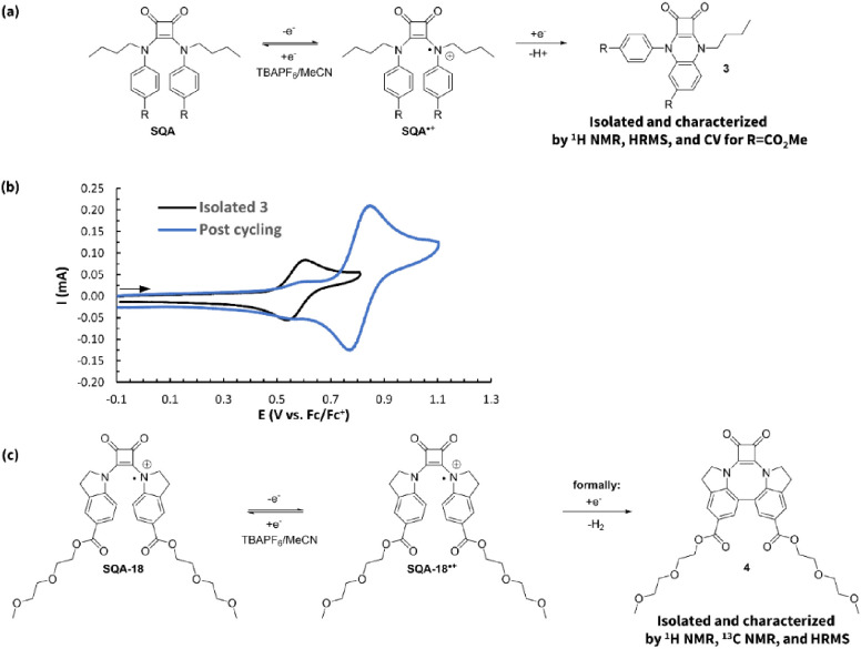
Nonaqueous organic redox flow batteries (N-ORFBs) are a promising technology for grid-scale storage of energy generated from intermittent renewable sources. Their primary benefit over traditional aqueous RFBs is the wide electrochemical stability window of organic solvents, but the design of catholyte materials, which can exploit the upper range of this window, has proven challenging. We report herein a new class of N-ORFB catholytes in the form of squaric acid quinoxaline (SQX) and squaric acid amide (SQA) materials. Mechanistic investigation of decomposition in battery-relevant conditions via NMR, HRMS, and electrochemical methods enabled a rational design approach to optimizing these scaffolds. Three lead compounds were developed: a highly stable one-electron SQX material with an oxidation potential of 0.51 V vs Fc/Fc+ that maintained 99% of peak capacity after 102 cycles (51 h) when incorporated into a 1.58 V flow battery; a high-potential one-electron SQA material with an oxidation potential of 0.81 V vs Fc/Fc+ that demonstrated negligible loss of redox active material as measured by pre- and postcycling CV peak currents when incorporated in a 1.63 V flow battery for 110 cycles over 29 h; and a proof-of-concept two-electron SQA catholyte material with oxidation potentials of 0.48 and 0.85 V vs Fc/Fc+ that demonstrated a capacity fade of just 0.56% per hour during static H-cell cycling. These findings expand the previously reported space of high-potential catholyte materials and showcase the power of mechanistically informed synthetic design for N-ORFB materials development.


Conflict of interest statement

The authors declare no competing financial interest.

Figures

Figure 1
Figure 1
Generalized schematic of a redox flow battery during charging.
Figure 2
Figure 2
(a) Selected catholyte materials. (b) Structures and potentials of the top-performing squaramide materials described in this work.
Figure 3
Figure 3
(a) Two-step synthesis of SQX-2 from commercially available materials. (b) CV of SQX-2 (5 mM in 0.5 M TBAPF6/MeCN) with a scan rate of 100 mV s–1. (c) Static oxidative H-cell cycling data between SQX-2 and SQX-2+, showing discharge capacity and Coulombic efficiency vs cycle number for 5 mM SQX-2 in 0.5 M TBAPF6/MeCN.
Figure 4
Figure 4
Oxidation potential and one-electron H-cell cycling stability of SQX derivatives SQX-1 to SQX-5. Solubility for SQX-1 was determined by a UV–vis calibration curve in an electrolyte solution of 500 mM TBAPF6 in MeCN, per Supporting Information page S25.
Figure 5
Figure 5
(a) Static oxidative H-cell cycling data between SQX-1 and SQX-1+ showing discharge capacity and Coulombic efficiency vs cycle number (100 cycles, 20.2 h) for the mixed solution of 5 mM SQX-1 and 5 mM 1+ in 0.5 M TBAPF6/MeCN. (b) Nernst curves showing potential versus capacity for the 2nd, 50th, and 100th cycles from the data shown in part (a). (c) CVs (500 mV s–1, glassy carbon electron) of the working side solution before and after the H-cell cycling of SQX-1 and SQX-1+ in a mixture of 5 mM SQX-1 and 5 mM 1+. (d) Variable scan CV (5 mM in 0.5 M TBAPF6/MeCN) of compound SQX-1 alone from 100 to 4000 mV s–1. (e) Plots of anodic and cathodic peak current densities (j) vs the square root of the sweep rate (ν1/2) for SQX-1. (f) Nicholson’s dimensionless parameter Ψ vs inverse square root of the sweep rate (ν–1/2) for SQX-1.
Figure 6
Figure 6
(a) Electrochemical reactions of the anolyte and catholyte during operation of a flow battery. (b) Flow cycling data showing charge and discharge capacities and Coulombic and energy efficiencies vs cycle number for a flow battery made with a mixture of SQX-1 (100 mM) and 1+ (100 mM) in 0.5 M TBAPF6/MeCN. Rebalancing of the cell was performed after 80 cycles and 100 cycles. (c) Nernst curves showing potential vs capacity for cycles 2, 25, and 102. (d) CVs (100 mV s–1) before and after flow cell cycling of SQX-1 and 1+ for both the anolyte and the catholyte sides of the battery. All solutions were diluted in a 1:19 ratio with 0.5 M TBAPF6/MeCN before acquisition. (e) Electrochemical impedance spectroscopy (EIS) on the flow cell before cycling, after 80 cycles, before cycle 81 (after first rebalancing), after cycle 100, and before cycle 101 (after second rebalancing).
Figure 7
Figure 7
Strategy for the development of our second generation of high oxidation potential squaramides (SQA) based upon a two-aniline core.
Figure 8
Figure 8
(a) CV of SQA-3 (5 mM in 0.5 M TBAPF6/MeCN) with a scan rate of 100 mV s–1. (b) Static oxidative H-cell cycling data between SQA-3 and SQA-3+ showing discharge capacity and Coulombic efficiency vs cycle number for 5 mM SQA-3 in 0.5 M TBAPF6/MeCN. (c) Proposed dimerization reaction of the radical cation SQA-3+.
Figure 9
Figure 9
Oxidation potential, one-electron H-cell cycling stability, and ratio of Ipa,3/Ipa,SQA after 100 cycles where Icp,3 is the peak anodic current corresponding to the byproduct 3, and Ipa,SQA is the residual peak anodic current corresponding to the parent SQA. Solubility for SQA-1 was determined by a UV–vis calibration curve in an electrolyte solution of 500 mM TBAPF6 in MeCN, per Supporting Information page S26. Notes: nd = not detected. (i) % fade/h following peak discharge capacity. (ii) Significant decomposition made it impossible to definitively detect via postcycling CV. (iii) None could be definitively detected via postcycling CV.
Figure 10
Figure 10
(a) Identification of intramolecular cyclization byproduct 3. (b) CVs of 3R=CO2Me (3.5 mM in 0.5 M TBAPF6/MeCN) overlaid with a CV of SQA-6 taken from the working reservoir after 100 static H-cell charge–discharge cycles. Both CVs were acquired at a scan rate of 500 mV s–1. (c) Identification of intramolecular biaryl byproduct 4 from the radical cation of indoline squaramide SQA-18.
Figure 11
Figure 11
(a) Structures of SQA-1 and viologens 52+ and 62+. (b) Comparison of discharge capacity vs cycle number for galvanostatic cycling of SQA-1 and SQA-1+ for the mixed solution of 5 mM SQA-1 and 5 mM 52+ in 0.5 M TBAPF6/MeCN (100 cycles, 19.6 h), and CCCV cycling of SQA-1 and SQA-1+ for the mixed solution of 5 mM SQA-1 and 5 mM 62+ in 0.5 mM TBAPF6/MeCN (100 cycles, 29.67 h, cutoffs: + 200 mV from E1/2, 0.1 mA). (c) Discharge capacity and Coulombic efficiency vs cycle number for galvanostatic cycling from (b). (d) CVs (500 mV s–1, glassy carbon electrode) of the working side solution before and after galvanostatic H-cell cycling of SQA-1 and SQA-1+ in a mixture of 5 mM SQA-1 and 5 mM 52+. (e) Discharge capacity and Coulombic efficiency vs cycle number for CCCV cycling from (b). (f) CVs (500 mV s–1, glassy carbon electron) of the working side solution before and after galvanostatic H-cell cycling of SQA-1 and SQA-1+ in a mixture of 5 mM SQA-1 and 5 mM 62+. Maximum theoretical discharge capacity is 0.67 mA h
Figure 12
Figure 12
(a) Electrochemical reactions of the anolyte and catholyte during operation of a flow battery. (b) Flow cycling data showing charge and discharge capacities and Coulombic and energy efficiencies vs cycle number for a flow battery made with a mixture of SQA-1 (50 mM) and 62+ (50 mM) in 0.5 M TBAPF6/MeCN. (c) Nernst curves showing potential versus capacity for cycles 10, 25, 95, and 110. (d) CVs (500 mV s–1) before and after flow cell cycling of SQA-1 and 62+ for both the anolyte and catholyte sides of the battery. All solutions were diluted in a 1:19 ratio with 0.5 M TBAPF6/MeCN before acquisition. (e) Electrochemical impedance spectroscopy (EIS) on the flow cell before cycling, after 45 cycles, and before cycle 93 (after rebalancing).
Figure 13
Figure 13
Oxidation potential and two-electron H-cell cycling stability of SQA 2, 3, 19, and 20.
Figure 14
Figure 14
(a) Static oxidative two-electron H-cell cycling data between SQA-2 and SQA-22+ (5 mM in 0.5 M TBAPF6/MeCN) showing discharge capacity and Coulombic efficiency vs cycle number. (b) Pre- and postcycling static H-cell cycling CV overlay of SQA-2 (5 mM in 0.5 M TBAPF6/MeCN) with a scan rate of 500 mV s–1. (c) Nernst curves showing potential vs capacity for cycles 2, 50, and 100. (d) Variable scan CV (5 mM in 0.5 M TBAPF6/MeCN) of compound SQA-2 from 100 to 4000 mV s–1. (e) Plots of anodic and cathodic peak current densities (j) vs the square root of the sweep rate (ν1/2) for SQA-2. (f) Nicholson’s dimensionless parameter Ψ vs inverse square root of the sweep rate (ν–1/2) for SQA-2.

References

    1. Calvin K.; Dasgupta D.; Krinner G.; Mukherji A.; Thorne P. W.; Trisos C.; Romero J.; Aldunce P.; Barrett K.; Blanco G., et al. IPCC, 2023: Climate Change 2023: Synthesis Report. Contribution of Working Groups I, II and III to the Sixth Assessment Report of the Intergovernmental Panel on Climate Change. In First Intergovernmental Panel on Climate Change (IPCC), The Core Writing Team Lee H.; Romero J., Eds.; IPCC: Geneva, Switzerland, 2023.
    1. Technical Summary. In Climate Change 2022 - Mitigation of Climate Change; Intergovernmental Panel on Climate Change (IPCC), The Core Writing Team; Lee H.; Romero J., Eds.; Cambridge University Press, 2023; pp. 51–148..
    1. Luz T.; Moura P. 100% Renewable Energy Planning with Complementarity and Flexibility Based on a Multi-Objective Assessment. Appl. Energy 2019, 255, 113819. 10.1016/j.apenergy.2019.113819. - DOI
    1. Jafari M.; Botterud A.; Sakti A. Decarbonizing Power Systems: A Critical Review of the Role of Energy Storage. Renew. Sustainable Energy Rev. 2022, 158, 112077. 10.1016/j.rser.2022.112077. - DOI
    1. Teleke S.; Baran M. E.; Bhattacharya S.; Huang A. Q. Rule-Based Control of Battery Energy Storage for Dispatching Intermittent Renewable Sources. IEEE Trans. Sustainable Energy 2010, 1, 117–124. 10.1109/TSTE.2010.2061880. - DOI