. 2024 Mar 5;15(4):2114-2132.
doi: 10.1364/BOE.516515. eCollection 2024 Apr 1.

Dual modality intravascular catheter system combining pulse-sampling fluorescence lifetime imaging and polarization-sensitive optical coherence tomography

Affiliations

Dual modality intravascular catheter system combining pulse-sampling fluorescence lifetime imaging and polarization-sensitive optical coherence tomography

Julien Bec et al. Biomed Opt Express. .

Abstract

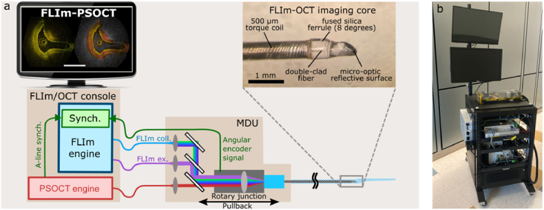
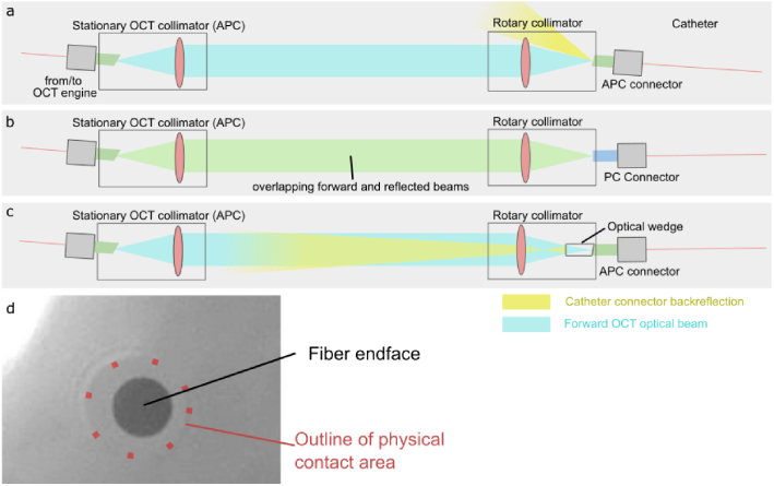
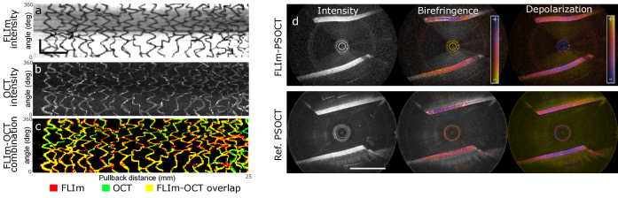
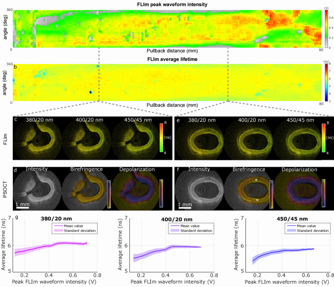
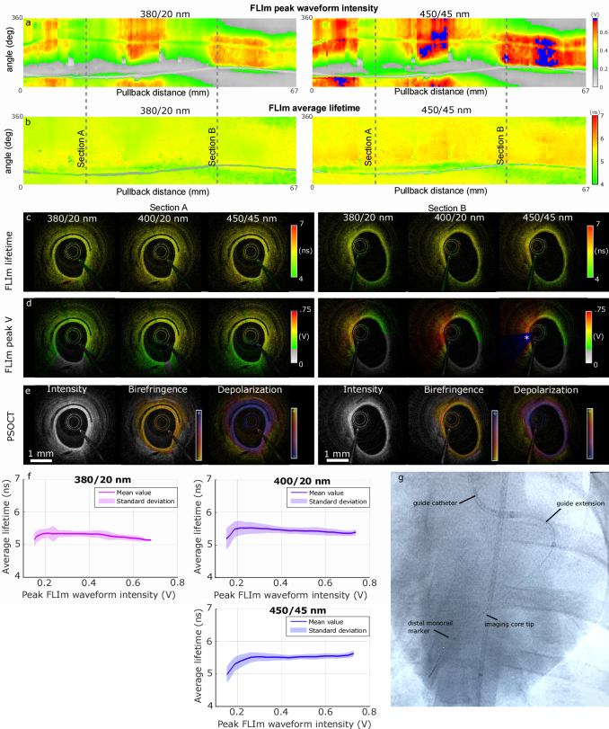
The clinical management of coronary artery disease and the prevention of acute coronary syndromes require knowledge of the underlying atherosclerotic plaque pathobiology. Hybrid imaging modalities capable of comprehensive assessment of biochemical and morphological plaques features can address this need. Here we report the first implementation of an intravascular catheter system combining fluorescence lifetime imaging (FLIm) with polarization-sensitive optical coherence tomography (PSOCT). This system provides multi-scale assessment of plaque structure and composition via high spatial resolution morphology from OCT, polarimetry-derived tissue microstructure, and biochemical composition from FLIm, without requiring any molecular contrast agent. This result was achieved with a low profile (2.7 Fr) double-clad fiber (DCF) catheter and high speed (100 fps B-scan rate, 40 mm/s pullback speed) console. Use of a DCF and broadband rotary junction required extensive optimization to mitigate the reduction in OCT performance originating from additional reflections and multipath artifacts. This challenge was addressed by the development of a broad-band (UV-visible-IR), high return loss (47 dB) rotary junction. We demonstrate in phantoms, ex vivo swine coronary specimens and in vivo swine heart (percutaneous coronary access) that the FLIm-PSOCT catheter system can simultaneously acquire co-registered FLIm data over four distinct spectral bands (380/20 nm, 400/20 nm, 452/45 nm, 540/45 nm) and PSOCT backscattered intensity, birefringence, and depolarization. The unique ability to collect complementary information from tissue (e.g., morphology, extracellular matrix composition, inflammation) with a device suitable for percutaneous coronary intervention offers new opportunities for cardiovascular research and clinical diagnosis.


Conflict of interest statement

The authors declare that there are no conflicts of interest related to this article.

Figures

Fig. 1.
Fig. 1.
Overall description of the hybrid intravascular imaging system. FLIm and PSOCT engines are located in the console. Actuation (rotation, pullback) of the motor drive unit (MDU) is controlled by the FLIm engine. Synchronization of FLIm data acquisition and PSOCT data acquisition is performed by the FLIm engine, where the PSOCT A-line synchronization signal and the rotation index of the MDU angular encoder are saved with a digitizer sharing a clock with the FLIm data acquisition. The catheter consists of a double-clad fiber (DCF) enclosed in a 2-layer torque coil. A fused silica ferrule improves reliability of the freeform micro-optic assembly by increasing the adhesive bond area, isolating the optics from forces that may be transferred by the torque coil, and preventing the micro-optics from contacting the sheath. An 8-degree angle at the interface with the micro-optics reduces the back-reflection of the optical adhesive interface (a). The FLIm-PSOCT system is packaged in a compact cart that can be easily transported to facilitate validation in animal model (b).
Fig. 2.
Fig. 2.
Schematic of free-space fiber coupling between stationary OCT collimator and rotary catheter collimator (steering mirrors omitted for simplicity). APC to APC junction provides the highest return loss but requires the catheter connector to be angled by 4 degrees to ensure efficient coupling (a). This configuration is mechanically imbalanced and not suitable for high-speed rotation. APC to PC rotary junction adopted in earlier implementation ensures that optical beam and catheter connector are concentric with the rotation axis, but the back reflection observed in the catheter proximal fiber facet leads to a low return loss of ∼14 dB, negatively affecting the system sensitivity (b). The fiber receptacle of the rotary collimator used for the FLIm-PSOCT system presented an additional cylindrical “wedge” element with an 8-degree interface with the catheter APC connector, keeping the rotation assembly balanced (c). With this design, the back-reflection generated from the air/glass interface occurs on the proximal end of the wedge, far from the collimator’s focal plane, which ensures high return loss (44 dB). The APC interface between the distal face of the wedge and the catheter connector ensures that return losses remain high even if physical contact were to be lost due to wear or contamination of that interface. This design is suitable for simultaneous UV/Vis/NIR operation and does not require any index matching fluid. Close-up of the interface between the catheter connector and the wedge, imaged through the wedge, visualizing the area of physical contact between the angle-polished domed ferrule and the wedge. Its extension beyond the cladding ensures that the insertion of the wedge is not leading to reduction in the optical coupling efficiency to and from both core and inner cladding of the DCF (d).
Fig. 3.
Fig. 3.
OCT background and signal analysis. The OCT background was measured for the FLIm-PSOCT DCF imaging core in air, in water and for a reference single-mode commercial OCT catheter imaging core. The delay was set to maximize the sensitivity where tissue is expected to be present during use (a). Sharp reflections from the fiber to distal optics are visible for the DCF probe, reflection from the distal optics exit face is clearly visible for all probes. A DCF artifact caused by the inner-cladding propagation of light backscattered at the exit surface is observed when the DCF core is tested in air. The maximum distance between exit surface and DCF artifact of 4.2 mm is consistent with what is expected from the catheter length and core and inner cladding mismatch. When tested in water, the reflection from the distal optics exit surface is reduced by approximately 10 dB and the associated DCF artifact is suppressed. In that configuration, the background of the FLIm-PSOCT DCF imaging core is better than what is obtained from a clinical imaging core that relies on a single-mode fiber. Imaging of a 0.5-mm thick ABS sheet demonstrates that both probes lead to similar sensitivities (b). The DCF artifact caused by the sample starts 4.2 mm closer than the object. It leads to 2-4 dB additional noise in the imaging region compared to the SMF probe. Images of background and test object demonstrates that despite the presence of DCF artifacts, the DCF probe provides images comparable to the reference SMF probe (c,d).
Fig. 4.
Fig. 4.
Coregistration and birefringence phantom. A stent deployed in a fluorescent acrylic tubular phantom provided both FLIm (a) and OCT contrast (b). Binary masks were generated from FLIm intensity and OCT backscattered intensity and combined to demonstrate registration (c). Both modalities are spatially registered since FLIm and OCT optical beams are concentric, but synchronization of both subsystems is required to achieve accurate coregistration, as demonstrated in the overlap en face image. Imaging of the birefringence phantom was performed for the FLIm-PSOCT hybrid system and a reference PSOCT system [21]. Both systems are able to characterize the layered birefringence of the polymer sheets. Scale bars: 3 mm.
Fig. 5.
Fig. 5.
Ex vivo FLIm-PSOCT imaging of swine coronary artery segment. Demonstrating the performance of the hybrid system in artery specimen is key to ensure that FLIm and PSOCT parameters can be extracted from samples with optical properties (fluorescence, scattering, birefringence, attenuation) that are similar to the target application. En face maps of peak fluorescence intensity (a) and average lifetime (b) demonstrate that consistent average lifetime values can be successfully extracted despite large variations of signal intensity. Cross sections are provided in two areas of the vessel (c/d: side branches, e/f: large vessel diameter) FLIm average lifetime encoded B-scans demonstrate uniform lifetime values. The OCT backscatter intensity image demonstrates clear visualization of media, adventitia, and perivascular tissue, with a penetration depth of at least 1 mm. High birefringence associated with high smooth muscle cell content is observed in the media (d, f). As expected, the demarcation between media and adventitia based on birefringence is less clear when the optical beam is crossing the media at a shallow angle (f, location marked with *): in that configuration, the muscle fibers are more closely aligned with the beam and thus birefringence is reduced. The depolarization is uniform and low due to the absence of lipid pools in healthy vessels (d, f). Display of mean and standard deviation of average lifetimes for the 380, 400 and 450 nm spectral bands shows a reduction of average lifetime as the wavelength increases (g). This finding is consistent with a relative increase in elastin-to-collagen fluorescence contribution at longer wavelength [15]. For each spectral band and intensity level, we also report a low standard deviation of the measured lifetime (∼0.1 to 0.2 ns), which increases with decreasing intensity. A modest but very consistent reduction of the average lifetime with decreasing signal intensity was also observed (see discussion section).
Fig. 6.
Fig. 6.
In vivo FLIm-PSOCT imaging of swine coronary artery segment. The system’s ability to acquire data in realistic conditions was validated by acquiring data in both left anterior descending and circumflex coronary arteries. En face images in the 370-nm and 450-nm bands demonstrate large variations of signal due to variations in probe to wall distance (a), but consistent lifetime values can be recovered as long as the peak signal voltage as above 0.2 V (b). Bimodal overlay showing average lifetime (c) and peak voltage (d) on OCT B-scans are provided for sections A and B. In section A, the smaller vessel diameter and close to centered position of the catheter in the lumen enables accurate lifetime measurement over the entire lumen circumference. In section B, areas of low signal led to an underestimation of the lifetime, whereas the saturated signal in the 450-nm band (location marked with *) does not seem to prevent accurate estimation of the lifetime. OCT intensity, birefringence and depolarization B-scans (e), provided for sections A and B, highlight the reduced vessel wall thickness in this young animal. The media birefringence is observed in both sections with, as expected, more contrast present in locations where the OCT beam is normal to the lumen. The evaluation of average lifetime versus signal intensity shows limited lifetime variability for intensities above approximately 0.2 V (f). This information is key to understand if variations of lifetime observed across the sample are driven by changes in composition or artifacts due to low signal. Fluoroscopy image demonstrating the placement of the catheter in the left anterior descending coronary artery (g).

Similar articles

Cited by

References

    1. Virani S. S., Alonso A., Aparicio H. J., et al. , “Heart disease and stroke statistics—2021 update,” Circulation 143(8), E254–E743 (2021).10.1161/CIR.0000000000000950 - DOI - PubMed
    1. Bentzon J. F., Otsuka F., Virmani R., et al. , “Mechanisms of plaque formation and rupture,” Circ. Res. 114(12), 1852–1866 (2014).10.1161/CIRCRESAHA.114.302721 - DOI - PubMed
    1. Otsuka F., Kramer M. C. A., Woudstra P., et al. , “Natural progression of atherosclerosis from pathologic intimal thickening to late fibroatheroma in human coronary arteries: a pathology study,” Atherosclerosis 241(2), 772–782 (2015).10.1016/j.atherosclerosis.2015.05.011 - DOI - PMC - PubMed
    1. Virmani R., Burke A. P., Farb A., et al. , “Pathology of the vulnerable plaque,” J. Am. Coll. Cardiol. 47(8 Suppl), C13–C18 (2006).10.1016/j.jacc.2005.10.065 - DOI - PubMed
    1. Bourantas C. V., Jaffer F. A., Gijsen F. J., et al. , “Hybrid intravascular imaging: recent advances, technical considerations, and current applications in the study of plaque pathophysiology,” Eur. Heart J. 38(6), 400–412 (2017).10.1093/eurheartj/ehw097 - DOI - PMC - PubMed