Review
. 2024 Apr 18;15(1):3328.
doi: 10.1038/s41467-024-46753-3.

Materials design for hypersonics

Affiliations
Review

Materials design for hypersonics

Adam B Peters et al. Nat Commun. .

Abstract

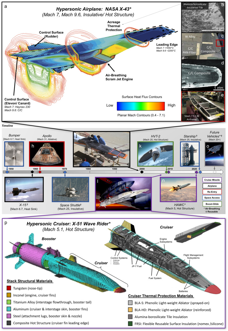
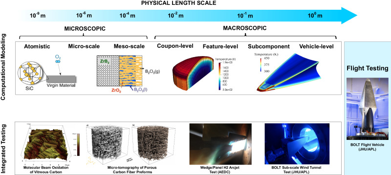
Hypersonic vehicles must withstand extreme conditions during flights that exceed five times the speed of sound. These systems have the potential to facilitate rapid access to space, bolster defense capabilities, and create a new paradigm for transcontinental earth-to-earth travel. However, extreme aerothermal environments create significant challenges for vehicle materials and structures. This work addresses the critical need to develop resilient refractory alloys, composites, and ceramics. We will highlight key design principles for critical vehicle areas such as primary structures, thermal protection, and propulsion systems; the role of theory and computation; and strategies for advancing laboratory-scale materials to manufacturable flight-ready components.


Conflict of interest statement

The authors declare no competing interests.

Figures

Fig. 1
Fig. 1. A brief history of hypersonic vehicles and an overview of key subsystems and materials for lifting body (airplane) and cruiser dominant designs.
a Computational fluid dynamics (CFD) simulation of the X-43 vehicle at a Mach 7 test condition with the engine operating. The solution includes internal (air-breathing scramjet engine) and external flow fields, including the interaction between the engine exhaust and vehicle aerodynamics. The image illustrates surface heat transfer on the vehicle (red is the highest heating) and flow field contours at the local Mach number. Structural components and the associated materials used for the design of the X-43 hypersonic vehicle are indicated: b Aluminoborosilicate insulation tile with an emissive coating used for acreage protection thermal protection; c nose and leading-edge design integrating carbon composites and refractory tungsten alloy SD 180; d Sharp leading edge cross-section showing the carbon composite with a refractory Ir coating; e airframe of the vehicle composed of steel/aluminum skin and Al/Ti bulkheads. fn Timeline of hypersonic vehicle development spanning hypersonic airplanes, space access, re-entry, boost-glide vehicles, and cruise missile applications, where colors indicate the hypersonic vehicles configuration: f the first vehicle to reach hypersonic speeds, Project Bumper-WAC “Without Any Control” (1949), g the reusable X-15 research aircraft (1959), h Apollo re-entry capsules (1961-1972), (i) Space Shuttle (1972-2011), (j) NASA X-43 airplane (2001), k the HVT-2 boost-glide vehicle (2010-2012), i Boeing X-51 scramjet (2010-2013), m SpaceX Starship (hypersonic re-entry in 2024), n DARPA HAWC - hypersonic air-breathing concept, o a notional future hypersonic vehicle, p structural and thermal protection materials distribution on X-51 hypersonic booster and cruiser. (Image sources: NASA (af, h, i, j), (c) – adapted from Ref. , (d) – adapted from Ref. , U.S. Airforce (g, l, p), DARPA (k), Creative Commons – Offical SpaceX (m), U.S. Govt. images not subject to copywrite).
Fig. 2
Fig. 2. Leading edge thermal protection systems types and steady-state finite element (FE) simulations of aerodynamic heating of a leading edge, carried out for a range of structural materials and hypothetical hypersonic flight conditions.
a Illustration of passive leading edge (left) and thermal profile (right) across a 2D TZM leading-edge, considering passive thermal management; b illustration of semi-passive leading edge (left) and thermal profile (right) of a semi-passive Li heat pipe operating at 1500 K; c illustration of active leading edge (left) and thermal profile (right) showing transpiration where the incident heat flux is reduced by a factor of 2. d Illustration of the sharp leading-edge geometry used in these simulations with the following dimensions: 3 mm tip radius, 3-degree wedge angle, 5 cm span, 10 cm cord length. e Ashby map highlighting operational tradeoffs for metal alloy, UHTC, refractory alloy, and carbon-base material classes. f Ashby-style plot of the FE simulation results from passive leading edges, where: the y-axis is the normalized mechanical stress resulting from a thermal expansion gradient, and the x-axis is the normalized peak temperature at the tip where the heat flux is highest. Only 4 materials (IN-738, IN 625, SS304, GRCop-84) are not viable from a temperature standpoint (ignoring oxidation), whereas 8 (Ti-64, SiC, C-103, T-111, ZrB2, TaC, HfB2, and HfC) are not viable due to the expansion stress exceeding the yield strength of the material at that temperature. Constraints via oxidation will decrease the overall maximum operating temperature; there is limited availability on oxidation kinetics for these materials. g The culmination of (f) for different flight conditions is shown as a hypothetical hypersonic flight corridor, where each line represents the “survivability limit” for a monolithic material with this specific (sharp) wedge geometry; known flight conditions of the X-43A, X-15, and typical space re-entry are indicated for reference. Figure 1a adapted from Ref. .
Fig. 3
Fig. 3. Hypersonic wing leading edge designs and associated materials microstructures processed under using different conditions showing materials oxidation.
a Schematic drawings of wing leading-edge conceptual design using a monolithic ceramic segmented edge. b Photographs of monolithic ZrB2/20 vol% SiC leading edges shown before and after arcjet testing in the H2 arc-jet facility (Fig. 3) with failed ceramics due to oxidation and thermal shock. c Failed and successful coated-C/C X-43 leading edges following arc-jet for simulated flight conditions of Mach 10, 32 km altitude using 1475 W/cm2, 130 seconds. d HfB2-SiC UHTC nose cone subjected to a total 80 minutes of arc jet exposure at heat fluxes of 200 W/cm2. The sample formed an oxide layer and a SiC depletion zone, which leaves behind a porous oxide surface (e). f Depicts SEM cross sections of HfB2-SiC or HfB2-SiC-TaSi2 materials formed via hot pressing and/or field-assisted sintering and with or without TaSi2 additives. The images indicate how grain structure, oxide layer formation, and SiC depletion is dramatically impacted by processing conditions and the inclusion of tertiary phases. g Scanning electron microscope image cross-section of a UHTCMC incorporating Cf and high aspect ratio SiC. (Images from NASA and adapted from Refs. ,,).
Fig. 4
Fig. 4. Multi-scale modeling and testing framework for materials design and flight testing.
Length scales for both modeling and testing approaches span many orders of magnitude. Smaller-scale models inform and validate successively larger-scale tests. (Images adapted from,– with permission).

References

    1. Van Wie DM. Hypersonics: Past, present, and potential future. John Hopkins APL Tech. Dig. 2021;35:335–341.
    1. Voland RT, Huebner LD, McClinton CR. X-43A hypersonic vehicle technology development. Acta Astronautica. 2006;59:181–191. doi: 10.1016/j.actaastro.2006.02.021. - DOI
    1. Deminsky, M. A., Kochetov, I. V., Napartovich, A. P. & Leonov, S. B. Modeling of plasma assisted combustion in premixed supersonic gas flow. Int. J. Hyperson.8, 209–224 (2010).
    1. Eswarappa Prameela S, et al. Materials for extreme environments. Nat. Rev. Mater. 2023;8:81–88. doi: 10.1038/s41578-022-00496-z. - DOI
    1. Glass, D. Ceramic matrix composite (CMC) thermal protection systems (TPS) and hot structures for hypersonic vehicles. In 15th AIAA International Space Planes and Hypersonic Systems and Technologies Conference, 2682 (2008). Illustrates and describes the significant types of thermal protection systems and relevant materials for their design.