. 2024 Apr 25;15(1):3492.
doi: 10.1038/s41467-024-46682-1.

Multi-level, forming and filament free, bulk switching trilayer RRAM for neuromorphic computing at the edge

Affiliations

Multi-level, forming and filament free, bulk switching trilayer RRAM for neuromorphic computing at the edge

Jaeseoung Park et al. Nat Commun. .

Abstract

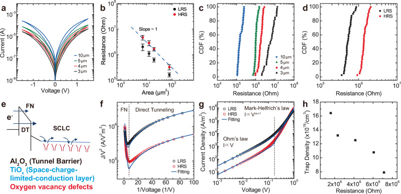
CMOS-RRAM integration holds great promise for low energy and high throughput neuromorphic computing. However, most RRAM technologies relying on filamentary switching suffer from variations and noise, leading to computational accuracy loss, increased energy consumption, and overhead by expensive program and verify schemes. We developed a filament-free, bulk switching RRAM technology to address these challenges. We systematically engineered a trilayer metal-oxide stack and investigated the switching characteristics of RRAM with varying thicknesses and oxygen vacancy distributions to achieve reliable bulk switching without any filament formation. We demonstrated bulk switching at megaohm regime with high current nonlinearity, up to 100 levels without compliance current. We developed a neuromorphic compute-in-memory platform and showcased edge computing by implementing a spiking neural network for an autonomous navigation/racing task. Our work addresses challenges posed by existing RRAM technologies and paves the way for neuromorphic computing at the edge under strict size, weight, and power constraints.


Conflict of interest statement

The authors declare no competing interests.

Figures

Fig. 1
Fig. 1. RRAM device stack and DC I-V switching characterization.
a Illustration of fabricated RRAM device stack and crossbar arrays. Bulk and filamentary RRAM switching mechanisms are compared. For bulk switching, the distribution of oxygen vacancies (VO) is modulated between TiOx and TiO2 layers. For filamentary switching, the VO filament formation and rupture occur near the bottom electrode. Scanning Electron Microscopy (SEM) images of fabricated b 16×16 crossbar array c single trilayer RRAM device, and d cross-section of a half-cut RRAM device. Filamentary switching characteristics of e S1 and f S2. g Coexistence of filamentary and bulk switching RRAM in S3. They show the opposite polarity due to the different resistance-switching mechanisms. Black arrows show the polarity of filamentary switching, while red arrows show polarity of bulk switching. h Bulk RRAM DC I-V characteristics of S4 without forming filaments. 50 cycles of DC sweeps perfectly overlap, showing highly uniform bulk switching.
Fig. 2
Fig. 2. Cross-sectional analysis of bulk RRAM device.
a Cross-sectional bright-field Transmission Electron Microscopy (TEM) image of trilayer bulk RRAM. The bright contrast of TiOx suggests a porous structure for the layer. b Atomic concentration profile measured by Scanning Transmission Electron Microscopy – Electron Energy Loss Spectroscopy (STEM-EELS) along the yellow arrow. All interfaces were determined based on the ion concentration and contrast in TEM image. The sputtered TiOx layer shows a smaller oxygen concentration which is lower than ALD TiO2 layer due to the VO in the layer. c STEM-EELS mapping of red dotted box region in a.
Fig. 3
Fig. 3. Electrical DC characterization of bulk RRAM devices.
a DC I-V switching curves of trilayer bulk RRAM with different diameter cells from 3 to 10 μm. b Double log plot of resistance vs. cell area. Area-scaling behavior with a slope of 1 suggests bulk switching of RRAM devices. Each size cell data is collected from 40 different devices measured at Vread = 0.1 V. c Cumulative distribution function (CDF) of bulk RRAM pristine resistance in different size cells. d CDF of LRS and HRS states programmed with DC sweep using bulk RRAM 5μm devices. e Band diagram of trilayer bulk RRAM. Al2O3 3 nm wide gap layer acts as a tunneling barrier where the direct/Fowler-Nordheim (FN) tunneling happen at small/large voltage region. In the TiOx layer, space-charge-limited-conduction (SCLC) occurs due to deep-level VO defects. f Log(J/V2) vs. 1/V curves of high resistance state (HRS) and low resistance state (LRS). Both states show similar conduction mechanisms. g Log J – log V plot of LRS and HRS states. In low voltage regime, current density follows the Ohm’s law (J∝V), while it follows the Mark-Helfrich’s law (J∝Vm+1) in high voltage regime. h Trap density (Nt) vs. device resistance curve. Nt is achieved by the fitting the experimentally measured data with our electrical conduction model.
Fig. 4
Fig. 4. Multilevel gradual switching characteristics of the bulk RRAM devices using pulse measurements.
a Multilevel switching using an identical pulse scheme for 32 different states. Set: −2.5 V, 500 μs/Reset: +1.5 V, 500 μs. b Multilevel switching using an identical pulse scheme for 32 different states. Set: −2.0 V, 5 ms/Reset: +1.0 V, 5 ms. c Multilevel switching using an incremental pulse scheme for 100 states. Set: −0.8 V to −2.78 V (−20 mV step)/Reset: +0.3 V to +0.993 V (+7 mV step). The transient current measurements using identical pulses d set (−2V) and e reset (+1.5 V) operations showing multi-level bulk switching without any abrupt current jumps (no filaments).
Fig. 5
Fig. 5. Row-differential voltage sensing using neuromorphic compute-in-memory platform with packaged bulk RRAM crossbar.
a Row-differential scheme. Two RRAMs sharing the same column represent positive and negative weights by applying opposite polarity voltage to respective WLs. b Dynamic range for switching for bulk RRAM. c Dynamic range enhancement using the row-differential scheme. For 100 levels, the row-differential scheme can increase the effective dynamic range up to ~170. d Photograph of neuromorphic compute-in-memory board with packaged bulk RRAM crossbar. e Conventional current sensing using transimpedance amplifier. f Switched-capacitor voltage-sensing circuit to achieve higher energy efficiency. g Measured and expected MVM outputs for the differential encoding.
Fig. 6
Fig. 6. Hardware implementation of SNN for a navigation/racing task.
a Examples of training and testing racetracks for navigation tasks. b Schematics of trained SNN (14 input/30 output neurons). c Weight map comparison between ideal weights and experimentally programmed weights on crossbars using the row-differential encoding. Two 16×16 crossbars were used for weight mapping. d Number of speed (Sp = 1, 1.6, 1.7) and steering angle (An = −0.23, 0, 0.17, 0.23) computations across navigation through all fifteen racetracks. Ideal software simulation and crossbar hardware implementation show highly consistent results. (Fitness score: 0.54 (Ideal S/W) vs. 0.43 (Crossbar H/W)). Ideal software vs. crossbar hardware computation of e steering angle and f speed during testing in the Catalunya map.

References

    1. Schuman CD, et al. Opportunities for neuromorphic computing algorithms and applications. Nat. Computat. Sci. 2022;2:10–19. doi: 10.1038/s43588-021-00184-y. - DOI - PubMed
    1. Jouppi, N. P. et al. In-datacenter performance analysis of a tensor processing unit. In Proceedings of the 44th annual international symposium on computer architecture, 1-12 (Association for Computing Machinery, 2017).
    1. Keckler SW, Dally WJ, Khailany B, Garland M, Glasco D. GPUs and the future of parallel computing. IEEE Micro. 2011;31:7–17. doi: 10.1109/MM.2011.89. - DOI
    1. Oh S, Huang Z, Shi Y, Kuzum D. The impact of resistance drift of phase change memory (PCM) synaptic devices on artificial neural network performance. IEEE Electron Device Lett. 2019;40:1325–1328. doi: 10.1109/LED.2019.2925832. - DOI
    1. Shi Y, et al. Performance prospects of deeply scaled spin-transfer torque magnetic random-access memory for in-memory computing. IEEE Electron Device Lett. 2020;41:1126–1129. doi: 10.1109/LED.2020.2995819. - DOI