. 2024 Apr 21;14(4):531.
doi: 10.3390/life14040531.

Impact of Structural Compliance of a Six Degree of Freedom Joint Simulator on Virtual Ligament Force Calculation in Total Knee Endoprosthesis Testing

Affiliations

Impact of Structural Compliance of a Six Degree of Freedom Joint Simulator on Virtual Ligament Force Calculation in Total Knee Endoprosthesis Testing

Eric Kleist et al. Life (Basel). .

Abstract

The AMTI VIVO™ six degree of freedom joint simulator allows reproducible preclinical testing of joint endoprostheses under specific kinematic and loading conditions. When testing total knee endoprosthesis, the articulating femoral and tibial components are each mounted on an actuator with two and four degrees of freedom, respectively. To approximate realistic physiological conditions with respect to soft tissues, the joint simulator features an integrated virtual ligament model that calculates the restoring forces of the ligament apparatus to be applied by the actuators. During joint motion, the locations of the ligament insertion points are calculated depending on both actuators' coordinates. In the present study, we demonstrate that unintended elastic deformations of the actuators due to the specifically high contact forces in the artificial knee joint have a considerable impact on the calculated ligament forces. This study aims to investigate the effect of this structural compliance on experimental results. While the built-in algorithm for calculating the ligament forces cannot be altered by the user, a reduction of the ligament force deviations due to the elastic deformations could be achieved by preloading the articulating implant components in the reference configuration. As a proof of concept, a knee flexion motion with varying ligament conditions was simulated on the VIVO simulator and compared to data derived from a musculoskeletal multibody model of a total knee endoprosthesis.

Keywords: biomechanics; joint simulator; knee joint dynamics; multibody model; structural compliance; total knee endoprostheses.


Conflict of interest statement

The authors declare no conflict of interest.

Figures

Figure 1
Figure 1
Flowchart of paper’s structure.
Figure 2
Figure 2
VIVO joint simulator with mounted femoral and tibial knee implants and schematic depiction of DOF. Upper actuator with two rotational DOFs for flexion/extension and adduction/abduction; lower actuator providing omnidirectional translations and internal/external rotation.
Figure 3
Figure 3
Test setup for examination of structural compliance of the VIVO at the reference configuration with 0° rotation of the flexion arm. Tests were also conducted at 30°, 60°, and 90° flexion angles.
Figure 4
Figure 4
Results of structural compliance examination—vertical displacements of the lower actuator s1 over the vertical force F for different flexion arm rotations.
Figure 5
Figure 5
(a) Vertical displacements Δs1 and Δs2 of VIVO actuators and virtual ligament insertion points under vertical load. The elastic displacement Δs2 is not captured by the VIVO’s sensors and is instead assumed zero for ligament force calculation. (b) Decreasing ligament force of the exemplary ligament under increasing vertical force. Supposing a perfectly rigid upper actuator, neither actuator would move vertically (Δs1 = Δs2 = 0) and the curve would be constant at the starting value of 268 N.
Figure 6
Figure 6
Functionality of embedding templates. Shown parts are merged with epoxy resin: (a) femoral component: holder 1, embedding template 2, implant 3; (b) tibial component: tibia insert 4, embedding template 5, holder 6. Holders 1 and 6 feature coupling interfaces matching the VIVO’s actuators.
Figure 7
Figure 7
Setting of reference configuration and definition of virtual ligaments: (a) The relative position between implants obtained in the MBS is set kinematically; (b) a given initial vertical force is applied, causing both actuators to move up vertically by Δs. The resulting configuration is defined as reference configuration. (c) The virtual ligament insertion points are defined in the reference configuration. Virtual ligaments are visualized as springs. (d) Passive flexion motion is executed, during which the resulting force of all individual virtual ligament forces Flig is applied by the lower actuator.
Figure 8
Figure 8
Musculoskeletal multibody model: (a) open kinematic chain with bones and implants shown at different flexion angles. (b) Detailed view of the knee joint model (posterior–lateral view) with considered ligament bundles (MCL not visible, implants hidden for clarity). These ligaments were also considered in the VIVO experiments.
Figure 9
Figure 9
Results of passive flexion test on the VIVO in comparison to MBS simulation: (a) axial contact force on tibia; (b) tibia internal/external rotation; (c) femoral AP displacement. Anatomical directions are indicated by arrows on the vertical axis.
Figure 10
Figure 10
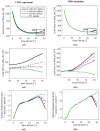
Results for different PCL stiffnesses during passive flexion. (a1a3): VIVO experiment; (b1b3): MBS simulation; (a1,b1) axial contact force on tibia; (a2,b2) detail view of (a1,b1) at high flexion angles; (a3,b3) femoral AP displacement.

References

    1. Zilles K., Tillmann B. Anatomie: Mit 121 Tabellen. Springer; Berlin/Heidelberg, Germany: 2010.
    1. Głowiński S., Krzyżyński T. An inverse kinematic algorithm for the human leg. J. Theor. Appl. Mech. 2016;54:53–61. doi: 10.15632/jtam-pl.54.1.53. - DOI
    1. Kebbach M. Computerbasierte Dynamische Funktionsanalyse des Endoprothetisch Versorgten Humanen Kniegelenks Mittels Muskuloskelettaler Mehrkörpersimulation. Dr. Hut; München, Germany: 2023.
    1. Maag C., Cracaoanu I., Langhorn J., Heldreth M. Total knee replacement wear during simulated gait with mechanical and anatomic alignments. Proc. Inst. Mech. Eng. H. 2021;235:515–522. doi: 10.1177/0954411921991269. - DOI - PubMed
    1. Ibrahim A., Yamomo G., Willing R., Towfighian S. Parametric Study of a Triboelectric Transducer in Total Knee Replacement Application. J. Intell. Mater. Syst. Struct. 2021;32:16–28. doi: 10.1177/1045389X20948581. - DOI - PMC - PubMed