. 2024 Sep 27;64(3):776-794.
doi: 10.1093/icb/icae014.

Using Pose Estimation and 3D Rendered Models to Study Leg-Mediated Self-righting by Lanternflies

Affiliations

Using Pose Estimation and 3D Rendered Models to Study Leg-Mediated Self-righting by Lanternflies

Theodore Bien et al. Integr Comp Biol. .

Abstract

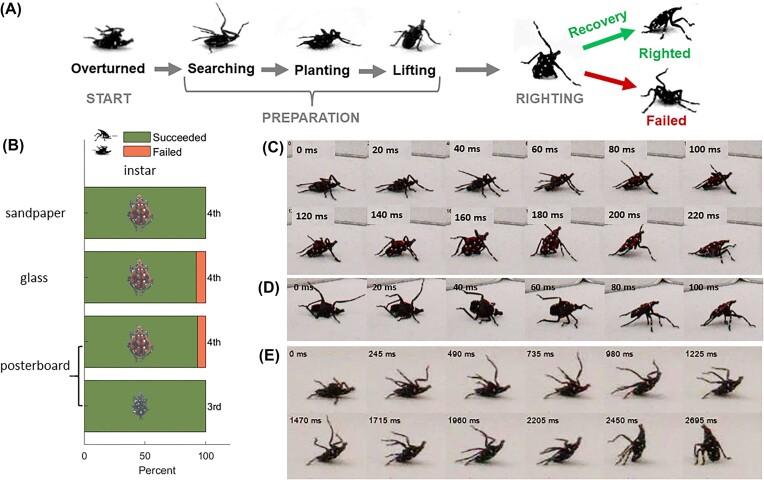
The ability to upright quickly and efficiently when overturned on the ground (terrestrial self-righting) is crucial for living organisms and robots. Previous studies have mapped the diverse behaviors used by various animals to self-right on different substrates, and proposed physical models to explain how body morphology can favor specific self-righting methods. However, to our knowledge, no studies have quantified and modeled all of an animal's limb motions during these complicated behaviors. Here, we studied terrestrial self-righting by immature invasive spotted lanternflies (Lycorma delicatula), an insect species that must frequently recover from being overturned after jumping and falling in its native habitat. These nymphs self-righted successfully in 92-100% of trials on three substrates with different friction and roughness, with no significant difference in the time or number of attempts required. They accomplished this using three stereotypic sequences of movements. To understand these motions, we combined 3D poses tracked on multi-view high-speed video with articulated 3D models created using photogrammetry and Blender rendering software. The results were used to calculate the mechanical properties (e.g., potential and kinetic energy, angular speed, stability margin, torque, force, etc.) of these insects during righting trials. We used an inverted physical pendulum model (a "template") to estimate the kinetic energy available in comparison to the increase in potential energy required to flip over. While these insects began righting using primarily quasistatic motions, they also used dynamic leg motions to achieve final tip-over. However, this template did not describe important features of the insect's center of mass trajectory and rotational dynamics, necessitating the use of an "anchor" model comprising the 3D rendered body model and six articulated two-segment legs to model the body's internal degrees of freedom and capture the role of the legs' contribution to inertial reorientation. This anchor elucidated the sequence of highly coordinated leg movements these insects used for propulsion, adhesion, and inertial reorientation during righting, and how they frequently pivot about a body contact point on the ground to flip upright. In the most frequently used method, diagonal rotation, these motions allowed nymphs to spin their bodies to upright with lower force with a greater stability margin compared to the other less frequently used methods. We provide a concise overview of necessary background on 3D orientation and rotational dynamics, and the resources required to apply these low-cost modeling methods to other problems in biomechanics.


Figures

Fig. 1
Fig. 1
(A) Fourth instar spotted lanternfly nymphs showing the definition of body length, Lbody.; see Supplementary Fig. S1A for the anatomical landmarks tracked on video and Supplementary Fig. S1B for the ventral view. (B) Arena and video camera used to film terrestrial self-righting. (C) Video frame showing the four camera views recorded of spotted lanternfly nymphs as they attempted to self-right. (D) Illustration of the geometry used to define the projection of the dorsal-ventral axis on the spatial Z direction used to quantify overturned vs righted orientation, −1 ≤ Zdv ≤ +1, and the tarsus (foot) z-position, ztarsus, in the body frame used to quantify foot motions. This figure shows a scenario when the body and spatial frames do not coincide. (E) Example of a 3D rendered model of a spotted lanternfly nymph used to estimate mechanical properties for modeling. (F) Illustration of a 3D model of the spotted lanternfly nymph’s body in the orientation used to define the body (xyz) and spatial (XYZ) frames in the reference orientation, and the relationship between coordinate axes, roll, pitch, and yaw rotations and Euler angles. (G) Frame from the animation showing tracked landmarks (see Supplementary Fig. S1A) with the 3D body model and six jointed rod legs. (H–J) Animation frames showing examples of the overturned, flipping, and righted resting poses defined in the text. (color online).
Fig. 2
Fig. 2
(A) Top view of a 3D model of a spotted lanternfly nymph (red) showing the definition of the stability margin. The support polygon (shaded region) is the convex hull formed by all body parts in contact with the ground. The stability margin (solid line) is the shortest distance from the boundary of the support polygon to the projection of the COM on the ground, while the ideal stability margin (dashed line) is the shortest distance from the support polygon’s in-plane centroid (×) to the boundary. (B) Schematic gravitational potential energy vs pose diagram showing the definition of the increase, ΔPE(t), in potential energy required to surmount the potential energy barrier starting at time t. Insets show sample images of a spotted lanternfly nymph in the overturned and righted poses (color online).
Fig. 3
Fig. 3
(A) Geometry used in defining angular velocity, ω, force, F, moment arm, r, and the moment of inertia, Irot, for a point mass, m. Geometry for defining moment of inertia for the general case of (B) a distributed mass and (C) a rod rotating about its center of mass (COM). The moment of inertia depends on the axis of rotation about the COM (D) and the distance, d, from the COM to the axis of rotation (E), as in the case of an inverted physical pendulum (F). The geometry for defining spin rotations about the COM and orbital motion of the COM is also shown in F. (G) Moments of inertia about each principal axis for the case where they correspond to the body’s roll, pitch, and yaw axes. (H) Calculation of the moment of inertia about an arbitrary axis of rotation, formula image (color online).
Fig. 4
Fig. 4
(A) Ethogram showing stereotypic poses assumed by spotted lanternfly nymphs during terrestrial self-righting. (B) Percent successful trials for each combination of substrate and life stage (instar) studied. (75 total trials per condition: N = 15, 5 trials/specimen). Sequences of closeup still images for (C) diagonal rotating about a pivot point on the caudal end (4th instar on sandpaper), (D) lifted rotating with the legs but not the body contacting the substrate (4th instar on sandpaper), and (E) pitching about a pivot point on the caudal end (3rd instar on posterboard). (C–E) Times relative to the first image shown at top left in each frame (color online).
Fig. 5
Fig. 5
Results of analysis of the tracked coordinates and 3D model plotted for diagonal rotating, lifted rotating, and pitching. Note that different time intervals were plotted for each righting mode to display data for approximately equal relative time intervals before and during active overturning (light gray shaded region) Supplementary Fig. S5A, B show plots for the other diagonal rotating and lifted rotating trials, and Supplementary Fig. S4C shows full results for the pitching trial. A–C show the z-component of the dorsal-ventral axis, which transitions from ≈ +1 when overturned to 0 at the flipping point to a final value ≥ −1 with the body pitched upward in the resting pose. D–F show the time behavior of gravitational potential energy of the whole insect and its body, and available kinetic energy, Kavail, computed from the inverted physical pendulum model (see text for details). These plots also illustrate the increase in potential energy, ΔPE(t), required to right at any given time. The plots in G–I compare the time dependence of ΔPE(t), Kavail, and the righting number, RN, used to characterize the contribution of inertial reorientation to righting. Note, especially, that the energy scale for pitching in (I) is approximately an order of magnitude lower than that for the other two methods. The plots in (J–L) compare the time behavior of the angular velocity of the body’s spin motion along its pitch and roll axes with the orbital angular velocity computed from the inverted physical pendulum model; see Fig. 3F for the definitions of ωorbital and ωspin; note that ωspin only includes contributions from roll and pitch rotations. M–O show the motion of the tarsi (feet) along in the z-axis in the body frame, as defined in Fig. 1D. The light gray vertical line denotes the flipping point (Zdv = 0) when the specimen transitions from overturned, and the dark gray vertical line the apex of its trajectory when total PE is at its maximum (Fig. 1H–J).
Fig. 6
Fig. 6
The measured pitch and roll angles vs time (black lines) for righting by (A, B) diagonal rotating, (C, D) lifted rotating, and (C) pitching shown superimposed on contour plots and heatmaps showing the gravitational potential energy (PE) landscape for the 3D rendered model of the spotted lanternfly body computed for each combination of elevation and bank angles with the lowest point on the body resting on the substrate. The actual measured values of the trajectory are also plotted using markers with colors corresponding to the computed whole insect potential energy at each time, using the colormap shown. Note that the heatmaps in A–D were computed using a 4th instar 3D model and (E) for a 3rd instar 3D model.

References

    1. Al Bitar L, Voigt D, Zebitz CPW, Gorb SN. 2010. Attachment ability of the codling moth Cydia pomonella L. to rough substrates. J Insect Physiol. 56:1966–72. - PubMed
    1. Avanesyan A, Maugel TK, Lamp WO. 2019. External morphology and developmental changes of tarsal tips and mouthparts of the invasive spotted lanternfly, Lycorma delicatula (Hemiptera: Fulgoridae). PLoS One. 14:e0226995. - PMC - PubMed
    1. Behm JE, Waite BR, Hsieh ST, Helmus MR. 2018. Benefits and limitations of three-dimensional printing technology for ecological research. BMC Ecol. 18:32. - PMC - PubMed
    1. Bien T, Alexander BH, White E, Hsieh ST, Kane SA. 2023. Sizing up spotted lanternfly nymphs for instar determination and growth allometry. PLoS One. 18:e0265707. - PMC - PubMed
    1. Burrows M, Cullen DA, Dorosenko M, Sutton GP. 2015. Mantises exchange angular momentum between three rotating body parts to jump precisely to targets. Curr Biol. 25:786–9. - PubMed

LinkOut - more resources