. 2024 Jul;11(26):e2401016.
doi: 10.1002/advs.202401016. Epub 2024 May 2.

Super-Droplet-Repellent Carbon-Based Printable Perovskite Solar Cells

Affiliations

Super-Droplet-Repellent Carbon-Based Printable Perovskite Solar Cells

Cuc Thi Kim Mai et al. Adv Sci (Weinh). 2024 Jul.

Abstract

Despite attractive cost-effectiveness, scalability, and superior stability, carbon-based printable perovskite solar cells (CPSCs) still face moisture-induced degradation that limits their lifespan and commercial potential. Here, the moisture-preventing mechanisms of thin nanostructured super-repellent coating (advancing contact angle >167° and contact angle hysteresis 7°) integrated into CPSCs are investigated for different moisture forms (falling water droplets vs water vapor vs condensed water droplets). It is shown that unencapsulated super-repellent CPSCs have superior performance under continuous droplet impact for 12 h (rain falling experiments) compared to unencapsulated pristine (uncoated) CPSCs that degrade within seconds. Contrary to falling water droplets, where super-repellent coating serves as a shield, water vapor is found to physisorb through porous super-repellent coating (room temperature and relative humidity, RH 65% and 85%) that increase the CPSCs performance for 21% during ≈43 d similarly to pristine CPSCs. It is further shown that water condensation forms within or below the super-repellent coating (40 °C and RH 85%), followed by chemisorption and degradation of CPSCs. Because different forms of water have distinct effects on CPSC, it is suggested that future standard tests for repellent CPSCs should include rain falling and condensate formation tests. The findings will thus inspire the development of super-repellent coatings for moisture prevention.

Keywords: carbon‐based printable perovskite solar cells; condensate formation test; rain falling tests; screen printing, stability; superrepellent coating.


Conflict of interest statement

The authors declare no conflict of interest.

Figures

Figure 1
Figure 1
Unencapsulated carbon‐based printable perovskite solar cells (CPSC): Pristine versus super‐repellent CPSCs. a) Schematic illustration of pristine CPSC (noncoated) showing the layered stack structure: FTO glass, a thin layer of compact TiO2, and the mesoporous layers (TiO2, ZrO2, and carbon electrode) infiltrated with perovskite with its b) wetting properties (measured advancing and receding contact angles) and c) scanning electron microscopy (SEM) micrograph (top view). d) Schematic illustration of super‐repellent CPSC coated with a thin nanostructured super‐repellent coating (commercially available Glaco) with its e) wetting properties (measured advancing and receding contact angles) and f) SEM micrograph (top view). g,h) Video frames captures from oscillation droplet tribometer measurements showing g) immobile ferrofluid droplet on one‐layer coated CPSC indicating no droplet bouncing (weak‐repellent CPSC) and h) highly mobile ferrofluid droplet on three‐layer coated CPSC resulted in droplet bouncing.
Figure 2
Figure 2
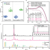
Integration of super‐repellent coating into CPSC. a) Statistical PCE for both forward and backward scans for 17 unencapsulated CPSCs before applying coating (pristine) and the same CPSC after applying coating (super‐repellent CPSCs) (from Batch I). b) J‐V curves of representative pristine and super‐repellent CPSCs with a measured aperture area of 0.64 cm2 under 1 Sun condition. c) XRD patterns of pristine and super‐repellent CPSC. Note that no additional peaks characteristic to super‐repellent coating (hydrophobic silica nanoparticles) were found primarily due to the amorphous structure of the coating.
Figure 3
Figure 3
Rain falling experiments. a) Schematic illustration of the setup showing pipette for water dropping (rain falling experiments), light, and mirror for sunlight simulation. Due to strong wetting, the pristine CPSC degraded in 10 s after water dropping started. The PV parameters were measured simultaneously. b) Current density versus time for pristine CPSC under illumination (0.4 Sun) and bias 0.695 V (V MPP). c) J–V curves of the pristine CPSC at the initial 1 and 0.4 Sun (attenuated due to the reflection through a mirror) and after the water dropping test under 0.4 Sun. d) Schematic illustration of the setup for super‐repellent CPSC showing droplet bouncing mechanism due to high repellency resulting in stable PCSC even after 12 h. e) Current density versus time of super‐repellent CPSC under illumination (0.4 Sun) and bias 0.67 V (V MPP). f) J–V curves of super‐repellent CPSC with the same parameters from (c). The active area was 0.64 cm2 (achieved by using a mask). The shapes and slopes of the J–V curves near Voc in (c) and (f) are identical for pristine and super‐repellent CPSCs, indicating that the coating does not affect the conductivity of the carbon electrode.
Figure 4
Figure 4
Dark storage test at room temperature (RT) and relative humidity (RH) 65% and 85%. Evolution of average (of forward and reverse scans) PV parameters of unencapsulated pristine and super‐repellent CPSCs (6 cells in each group) under 1 Sun (aperture area of 0.64 cm2). The aging test consists of two segments: segment 1 was conducted at RT and 65% RH for 864 h, and segment 2 was conducted at RT, 85% RH for 165 h. The presented values are average values for six different cells from each group. The distribution of PV parameters after each segment is reported in Figure S7 (Supporting Information).
Figure 5
Figure 5
Repelling mechanisms for different moisture (water) forms. a) Schematic illustration of shielding against bulk water showing blockage of mass transfer and resulting b) droplet bouncing from the super‐repellent CPSC. c) Schematic illustration of vapor absorption through the pores of the coating resulting in (d) perovskite crystal growth. e) Schematic illustration of condensation on super‐repellent CPSC shows condensate growth within (or even below) the coating. f) The graphs for supersaturation conditions and adsorption hysteresis characteristic of condensation from supersaturated vapor. The supersaturation graph shows the warm‐up curve for air and CPSC indicated time delay Δt of CPSC to reach the air temperature and temperature difference ΔT at which supersaturation occurs. After the CPSC equilibrate to air temperatures (ΔT  = 0) and RH 85%, due to adsorption hysteresis the amount of condensed water inside the sample does not decrease to the same amount during adsorbing water in the warm‐up time (e.g., stays at the position indicated with the red dot).

References

    1. Kojima A., Teshima K., Shirai Y., Miyasaka T., J. Am. Chem. Soc. 2009, 131, 6050. - PubMed
    1. Best Research‐Cell Efficiency Chart, https://www.nrel.gov/pv/cell‐efficiency.html (accessed: April 2024).
    1. Pescetelli S., Agresti A., Viskadouros G., Razza S., Rogdakis K., Kalogerakis I., Spiliarotis E., Leonardi E., Mariani P., Sorbello L., Pierro M., Cornaro C., Bellani S., Najafi L., Martín‐García B., Del Rio Castillo A. E., Oropesa‐Nuñez R., Prato M., Maranghi S., Parisi M. L., Sinicropi A., Basosi R., Bonaccorso F., Kymakis E., Di Carlo A., Nat. Energy 2022, 7, 597.
    1. Lee K.‐M., Chiu W.‐H., Tsai Y.‐H., Wang C.‐S., Tao Y.‐T., Lin Y.‐D., Chem. Eng. J. 2022, 427, 131609.
    1. Berger E., Bagheri M., Asgari S., Zhou J., Kokkonen M., Talebi P., Luo J., Nogueira A. F., Watson T., Hashmi S. G., Sustainable Energy Fuels 2022, 6, 2879.

LinkOut - more resources