

Control strategy for current limitation and maximum capacity utilization of grid connected PV inverter under unbalanced grid conditions
- PMID: 38698069
- PMCID: PMC11066046
- DOI: 10.1038/s41598-024-60244-x
Control strategy for current limitation and maximum capacity utilization of grid connected PV inverter under unbalanced grid conditions
Abstract
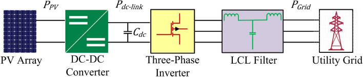
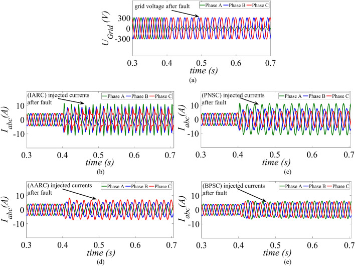
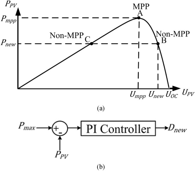
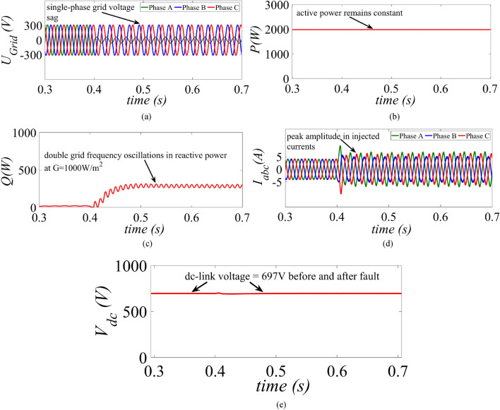
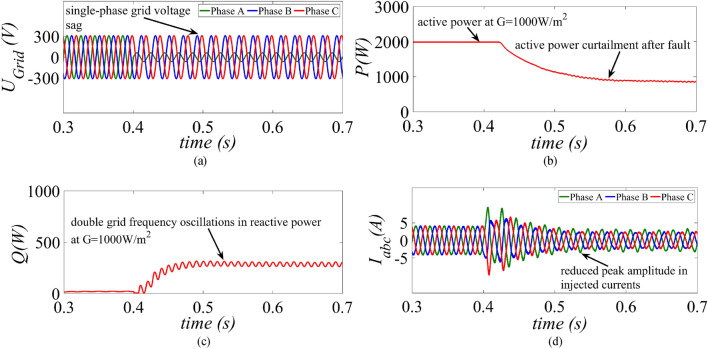
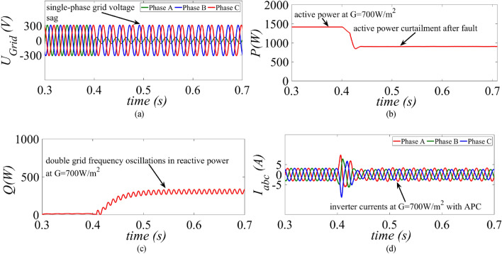
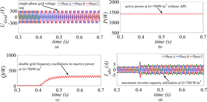
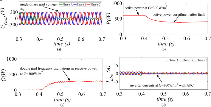
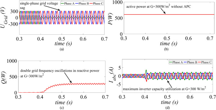
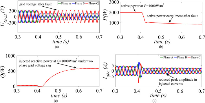
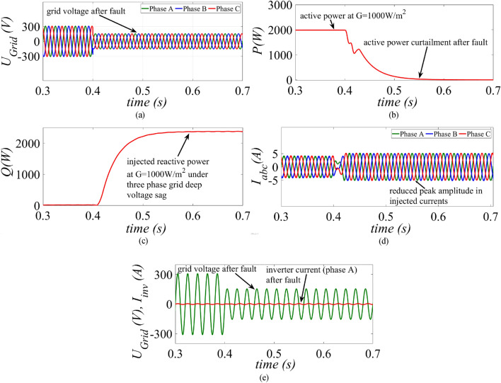
Under grid voltage sags, over current protection and exploiting the maximum capacity of the inverter are the two main goals of grid-connected PV inverters. To facilitate low-voltage ride-through (LVRT), it is imperative to ensure that inverter currents are sinusoidal and remain within permissible limits throughout the inverter operation. An improved LVRT control strategy for a two-stage three-phase grid-connected PV system is presented here to address these challenges. To provide over current limitation as well as to ensure maximum exploitation of the inverter capacity, a control strategy is proposed, and performance the strategy is evaluated based on the three generation scenarios on a 2-kW grid connected PV system. An active power curtailment (APC) loop is activated only in high power generation scenario to limit the current's amplitude below the inverter's rated current. The superior performance of the proposed strategy is established by comparison with two recent LVRT control strategies. The proposed method not only injects necessary active and reactive power but also minimizes overcurrent with increased exploitation of the inverter's capacity under unbalanced grid voltage sag.
Keywords: Active and reactive power control; Active power curtailment; Grid connected PV system; Inverter current limitation; Voltage stability.
© 2024. The Author(s).
Conflict of interest statement
The authors declare no competing interests.
Figures

References
-
- Krithiga S, Gounden NGA. Power electronic configuration for the operation of PV system in combined grid-connected and stand-alone modes. IET Power Electron. 2014;7(3):640–647. doi: 10.1049/iet-pel.2013.0107. - DOI
-
- Mahmoud K, Lehtonen M. Comprehensive analytical expressions for assessing and maximizing technical benefits of photovoltaics to distribution systems. IEEE Trans. Smart Grid (early access) 2021 doi: 10.1109/TSG.2021.3097508. - DOI
-
- Serban E, Ordonez M, Pondiche C. Voltage and frequency grid support strategies beyond standards. IEEE Trans. Power Electron. 2017;32(1):298–309. doi: 10.1109/TPEL.2016.2539343. - DOI
-
- Tang C-Y, Chen Y-T, Chen Y-M. PV power system with multimode operation and low-voltage ride-through capability. IEEE Trans. Ind. Electron. 2015;62(12):7524–7533. doi: 10.1109/TIE.2015.2449777. - DOI
-
- Perpinias II, Papanikolaou NP, Tatakis EC. Fault ride through concept in low voltage distributed photovoltaic generators for various dispersion and penetration scenarios. Sustain. Energy Technol. 2015;12:15–25.
Grants and funding
LinkOut - more resources
Full Text Sources
