. 2024 Apr 24:12:1353901.
doi: 10.3389/fbioe.2024.1353901. eCollection 2024.

Computational evaluation of wire position using separate vertical wire technique and candy box technique for the fixation of inferior pole patellar fractures: a finite element analysis

Affiliations

Computational evaluation of wire position using separate vertical wire technique and candy box technique for the fixation of inferior pole patellar fractures: a finite element analysis

Wei Fan et al. Front Bioeng Biotechnol. .

Abstract

The separate vertical wire (SVW) technique and the improved candy box (CB) technique have been proposed for treating inferior pole patellar fractures. However, there is still a lack of clear explanation regarding the location of the wire passing through the patella. Five models of SVW techniques were established in different positions. Finite element analysis was then conducted to determine the optimal bone tunnel position for the SVW technique. Based on these findings, six groups of finite element models were created for CB techniques. The maximum displacement and stress on both the patella and steel wire were compared among these groups under 100-N, 200-N, 300-N, 400-N, and 500-N force loads. The results indicated that, in the SVW technique, the steel wire group near the fracture end of the longitudinal bone tunnel showed minimal displacement and stress on the patella when subjected to different forces. On the other hand, in the CB technique, both the patella and wire experienced minimal stress when a transverse bone tunnel wire was placed near the upper posterior aspect of patella. In conclusion, the SVW technique may require the bone tunnel wire to be positioned near the fractured end of the lower pole of the patella. On the other hand, in CB technique, the transverse bone tunnel wire passing through the patella may be close to its upper posterior aspect. However, further validation is necessary through comprehensive finite element analysis and additional biomechanical experiments.

Keywords: candy box technique; finite element analysis; inferior pole patellar fractures; separate vertical wire technique; wire position.


Conflict of interest statement

The authors declare that the research was conducted in the absence of any commercial or financial relationships that could be construed as a potential conflict of interest.

Figures

FIGURE 1
FIGURE 1
Schematic diagram of separate vertical wire and candy box technology. (A) Front view of separate vertical wire technology. (B) Front view of candy box technology. (C) Side view of candy box technology. (a) Three separate vertical steel wires. (b) Upper 1/3 steel wires of the patellar tunnel. (c) Middle 1/3 steel wires of the patellar tunnel.
FIGURE 2
FIGURE 2
Schematic diagram of the research plan. (A) The first part of the diagram shows five vertical steel wires positioned at different locations. Line m is the midline of the patella. The intersection point between the starting point behind the fracture end and the stop point of the quadriceps tendon with line m is referred to as group c. Group b and group d intersect with line m at positions 2 mm above and below, respectively, under the same starting point condition. Similarly, group a and group e intersect with line m at positions 4 mm above and below, respectively. In total, there are five groups in the first part. (B) In Part 2, the diagram illustrates the positions of two horizontal steel wires. Line n represents a vertical line located 5 mm behind the articular surface of the patella, Line o represents a vertical line directly in front of the patella, Line s represents the midpoint line between lines o and n, Lines x and y represent vertical lines positioned 2 mm in front and behind line s, respectively. Steel wire g is considered to be in an optimal position based on Part 1 of the study. Point p is situated below line s, with a distance of 4 mm from steel wire g. Points p1, p2, and p3 are taken at positions that are 2 mm away from steel wire g along lines x, s, and y respectively, Points p4 and p5 are located above points p2 and p3 with an interval of 2 mm, Point p6 is positioned above point p5 with a distance of 2 mm. Overall, there are six groups included in Part 2.
FIGURE 3
FIGURE 3
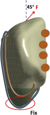
Schematic diagram of patella loading. The inferior pole of the patella is bound and constrained, the upper pole is loaded, and the arrow indicates the stretching direction. The orange circles represent the support of the medial and lateral condyles of the femur to the patella.
FIGURE 4
FIGURE 4
The schematic diagram of the research results in the first part. (A) Displacement nephogram under 500N force. (B) Stress nephogram of patella under 500N force. (C) Stress nephogram of steel wire under 500N force. (D) Histogram of the maximum displacement of different groups under different forces. (E) Histogram of the maximum stress of patella under different forces. (F) Histogram of the maximum stress of steel wire under different forces. Note: In this context, “a,b,c,d,e” represent different positions along the vertical wire.
FIGURE 5
FIGURE 5
The schematic diagram of the research results in the second part. (A) Displacement nephogram under 500N force. (B) Stress nephogram of patella under 500N force. (C) Stress nephogram of steel wire under 500N force. (D) Histogram of the maximum displacement of different groups under different forces. (E) Histogram of the maximum stress of patella under different forces. (F) Histogram of the maximum stress of steel wire under different forces. Note: In this context, p1, p2, p3, p4, p5, and p6 respectively represent different positions of the upper 1/3 of the wire.

References

    1. Amirouche F., Solitro G. F., Walia A., Gonzalez M., Bobko A. (2017). Segmental acetabular rim defects, bone loss, oversizing, and press fit cup in total hip arthroplasty evaluated with a probabilistic finite element analysis. Int. Orthop. 41 (8), 1527–1533. 10.1007/s00264-016-3369-y - DOI - PubMed
    1. Bonazza N. A., Lewis G. S., Lukosius E. Z., Roush E. P., Black K. P., Dhawan A. (2018). Effect of transosseous tunnels on patella fracture risk after medial patellofemoral ligament reconstruction: a cadaveric study. Arthroscopy 34 (2), 513–518. 10.1016/j.arthro.2017.08.267 - DOI - PubMed
    1. Chang C. W., Chen Y. N., Li C. T., Chung Y. H., Chang C. H., Peng Y. T. (2018). Role of screw proximity in the fixation of transverse patellar fractures with screws and a wire. J. Orthop. Surg. (Hong Kong) 26 (3), 230949901878970. 10.1177/2309499018789705 - DOI - PubMed
    1. Chen C. H., Chen Y. N., Li C. T., Chang C. W., Chang C. H., Peng Y. T. (2019). Roles of the screw types, proximity and anterior band wiring in the surgical fixation of transverse patellar fractures: a finite element investigation. BMC Musculoskelet. Disord. 20 (1), 99. 10.1186/s12891-019-2474-7 - DOI - PMC - PubMed
    1. Demirtaş Y., Katı Y. A. (2023). A novel patella fracture fixation technique: finite element analysis. Archives Orthop. trauma Surg. 143 (8), 5105–5115. 10.1007/s00402-023-04910-1 - DOI - PubMed

LinkOut - more resources