. 2024 Jun 6;187(12):3006-3023.e26.
doi: 10.1016/j.cell.2024.04.014. Epub 2024 May 13.

Vertebrate centromeres in mitosis are functionally bipartite structures stabilized by cohesin

Affiliations

Vertebrate centromeres in mitosis are functionally bipartite structures stabilized by cohesin

Carlos Sacristan et al. Cell. .

Abstract

Centromeres are scaffolds for the assembly of kinetochores that ensure chromosome segregation during cell division. How vertebrate centromeres obtain a three-dimensional structure to accomplish their primary function is unclear. Using super-resolution imaging, capture-C, and polymer modeling, we show that vertebrate centromeres are partitioned by condensins into two subdomains during mitosis. The bipartite structure is found in human, mouse, and chicken cells and is therefore a fundamental feature of vertebrate centromeres. Super-resolution imaging and electron tomography reveal that bipartite centromeres assemble bipartite kinetochores, with each subdomain binding a distinct microtubule bundle. Cohesin links the centromere subdomains, limiting their separation in response to spindle forces and avoiding merotelic kinetochore-spindle attachments. Lagging chromosomes during cancer cell divisions frequently have merotelic attachments in which the centromere subdomains are separated and bioriented. Our work reveals a fundamental aspect of vertebrate centromere biology with implications for understanding the mechanisms that guarantee faithful chromosome segregation.

Keywords: centromere; chromatin organization; chromosomal instability; cohesin; condensin; kinetochore; mitosis.


Conflict of interest statement

Declaration of interests The authors declare no competing interests.

Figures

None
Graphical abstract
Figure 1
Figure 1
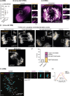
Subdomain organization of the vertebrate regional centromere (A–C) ExM (CENP-A, DAPI) of a metaphase RPE-1 cell. Arrowheads in inset: CENP-A subdomains. (B) Blow-ups of the dotted boxes in (A). (C) Line intensity profiles across centromere subdomains in (B). Distance between peaks is indicated. (D) Fraction of centromeres per cell with the indicated number of CENP-A subdomains. Complex: centromeres with >4 subunits or heterogenoeus shapes (mean ± SD of 4 independent experiments; n = 21 cells, 829 centromeres). (E) Distance between CENP-A subdomains in bipartite centromeres in ExM images (mean ± SD of 3 independent experiments, n = 240 centromeres). Large dots, independent experiments; small dots, single centromeres. (F) CENP-C immunostaining in stretched chromosomes. Arrowheads: CENP-C subdomains. (G) (Left) ExM image of CENP-A and CENP-B in PDNC4 cells with neocentromere in chromosome 4 (Neo4q21.3). (Right) Blow-up of the box in (G). Neo4q21.3 is recognized by the lack of CENP-B signal between sister centromeres; alphoid cen: a canonical centromere containing α-satellite repeats. Arrowheads: CENP-A subdomains. (H) ExM (ACA, anti-centromere antibody) of mouse embryonic fibroblast (MEF). Arrowheads: ACA subdomains. See also Figure S1J. (I) ExM (CENP-T) of a chicken DT40 cell. Arrowheads: CENP-T subdomains. (J) Cartoon depicting core centromere organization. Two subdomains (orange balls) are each associated to one chromosome arm. In all figures, NI, normalized intensity; Z, plane of z stack or maximum intensity projection of indicated planes. See also Figure S1.
Figure S1
Figure S1
Subdomain organization of the regional centromere of vertebrates, related to Figure 1 (A) 3D reconstructions of the centromeres shown in Figures 1A and 1B. (B–D) Representative ExM image of CENP-A in RPE-1 cells in metaphase (B). Blow-ups, centromeres enclosed in the boxes (C), and line intensity profiles across centromere subdomains (D). The distance between peaks is indicated. (E) Examples of tetrapartite centromeres. Asterisks: small subdomains; arrowheads: main two subdomains. (F and G) Immunostaining of CENP-A in HCT-116 cells imaged by confocal and STED microscopy. Numbered squares enclose the same centromeres in both conditions. Line intensity profiles across centromere subdomains (G). The distance between peaks is indicated. (H and I) iSIM live-cell imaging (lateral resolution ⁓125 nm) of a U2OS cell expressing mCherry-CENP-A and H2B-mNeon (H). Blow-ups of the orange box and other regions are shown on the right. Line intensity profiles across centromere subdomains (I). The distance between peaks is indicated. (J) Representative ExM image of a mouse embryonic fibroblast (MEF) immunostained with ACA (anti-centromere antibody). Arrowheads: ACA subdomains. The image belongs to the same cell shown in Figure 1H. Z specifies the plane of the z stack. NI, normalized intensity.
Figure 2
Figure 2
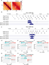
Bipartite mitotic centromeric chromatin organization of chicken Zcen (A) Hi-C map of 25 Mbp region surrounding Zcen (arrow) in G2 or in late prometaphase (T = 30 min after release from 1NM-PP1). 100 kb resolution. Data are from Gibcus et al. (B) Positions of capture oligo pairs (view points) (P1–P34) surrounding Zcen and the CENP-A ChIP-seq data to indicate the position of Z core centromere in wild-type (WT) CDK1as parental cell line used for this study. (C–E) Directionality of interactions at each view point in WT G2 cells (C), WT late prometaphase cells (D), and WT late prometaphase cells treated with nocodazole (E). Core centromere (CENP-A region) is marked by white box. Asymmetry of interaction is depicted by green upward bar (more interactions toward p arm) and by orange downward bar (more interactions toward q arm). x axis shows genomic DNA position on Z chromosome. Value on the y axis is the natural log of the number of interactions toward the p arm divided by the number of interactions toward the q arm. Only interactions with positions within a distance of 3–250 kbp of the viewpoint are included. The graph represents sum of two independent experiments. See also Figure S2.
Figure S2
Figure S2
Bipartite mitotic centromeric chromatin organization of chicken Zcen and 5cen, related to Figures 2B–2E, 6J, 6K, S6F, and S6G (A) Hi-C map of 2.5 MB region surrounding Zcen (arrow) in G2 or in late prometaphase (T = 30 min after release from 1NMPP1). 100 kb resolution. Data are taken from Gibcus et al. (B and C) CENP-A ChIP-seq data to indicate the regions of the Z (B) and 5 (C) core centromeres of WT, SMC2-AID, and SMC3-AID CDK1as subclone cell lines used for this study, and positions of capture oligos pairs (view points) surrounding (P1–P34) (B) and 5cen (P1–P27) (C). The core centromeric region is marked by a white box. Note: the core Zcen of SMC3-AID cells shifted toward the q arm by ∼10 kb compared with WT and SMC2-AID cells due to centromere migration in this clone. Similarly, the 5cen positions varied among homologous chromosomes (WT) and sub-cell lines. It appeared that 5 cen positions in SMC3-AID clones are almost identical between two 5 chromosomes. (D–H) Directionality of interactions at each view point of Zcen (D–F) and 5cen (G and H) in SMC3-AID G2 and late prometaphase cells in the presence and absence of auxin, as indicated. Depletion of SMC3 does not affect to the directionality of interactions (see also Figure 6K). Core centromeric region (defined by the presence of CENP-A) is marked by the white box. Asymmetry in interaction is depicted by green upward bar (more interactions toward p arm) and by orange downward bar (more interactions toward q arm). x axis shows genomic DNA position in chromosome Z (D–F) and 5 (G and H). Value on the y axis is the natural log of the number of interactions toward the p arm divided by the number of interactions toward the q arm; only interactions with positions within a distance of 3–250 kbp of the viewpoint are included. The graphs represent the sum of two independent experiments.
Figure 3
Figure 3
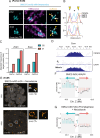
Kinetochore subdomains bind separate microtubule bundles (A and B) ExM (α-tubulin, CENP-C) of metaphase RPE-1 cell cold-treated before fixation (A). (Right) Blow-ups of the boxes and other regions of the indicated planes. Arrowheads: double k-fibers. (B) Line intensity profiles across kinetochore subdomains (arrows in CENP-C) and k-fibers (arrows in α-tubulin). (C) Fraction of centromeres per cell with the indicated number of CENP-C subdomains and k-fiber bundles (mean ± SD of 2 independent experiments; n = 11 cells, 466 centromeres). See also Figure S3. (D) Cartoon depicting the binding of independent microtubule bundles (purple filaments) to kinetochore subdomains (green balls). (E–G) 3D electron-tomography reconstruction showing k-fibers in HeLa cells (E). Blow-up, k-fiber with two microtubule bundles (yellow arrowheads), with the plus ends indicated with dark blue spheres. (Right) Kernel distance estimation plot of plus-end distribution along the xz axis. Fraction of k-fibers containing two distinct bundles (F). Average distance between the centers of masses of double bundles (G). (Mean ± SD, n = 3 cells, 289 k-fibers.) Analyses performed on data generated in Kiewisz et al. (H) ExM of a bipartite kinetochore (CENP-C), with one subdomain end-on attached and the other laterally attached via the fibrous corona (marked by CENP-E35). The cell was treated with 330 nM nocodazole. (I) Cartoon of image in (H). See also Figure S3.
Figure 4
Figure 4
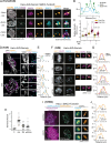
Biorientation of kinetochore subdomains in merotelic attachments (A) ExM image (α-tubulin, CENP-C) of an RPE-1 cell treated with ZM-447439. Blow-ups, merotelically attached kinetochores, where subdomains engage microtubules from opposite spindle poles. (B–D) ExM image (HEC1, CENP-C, CAP-H2) of an RPE-1 cell treated with ZM-744439 (B). Blow-ups, mono-oriented kinetochores, where both subdomains face the same spindle pole, and bioriented kinetochores with subdomains oriented toward opposite poles. (C) 3D reconstructions and (D) line intensity profiles across kinetochores 2 and 4. In bioriented kinetochores, CENP-C localizes between HEC-1 subdomains. (E) Cartoon depicting the relative distribution of HEC1, CENP-C, and CAP-H2 in mono-oriented and bioriented subdomains. (F and G) iSIM images (HEC1, CENP-C, CENP-B) of RPE-1 cells released from monastrol or treated with ZM-447439 (F). Arrowheads: stretched bioriented subdomains. Line intensity profiles across kinetochore subdomains (G). (H) Quantifications of the number of bioriented kinetochores per cell after monastrol release (mean ± SD of 2 independent experiments; DMSO: n = 38 cells, Mon. rel.: n = 41 cells; Student’s t test, two-tailed, unpaired) or ZM-447439 treatment (mean ± SD of 3 independent experiments: DMSO: n = 30 cells, ZM: n = 45 cells; Student’s t test, two-tailed, unpaired. p values are indicated). Large dots, independent experiments; small dots, single cells. (I) Distance between HEC1 subdomains in mono-oriented and stretched kinetochores. Monastrol release (left) (mean ± SD, pooled kinetochores, 2 independent experiments; DMSOMono-oriented, n = 323, DMSOBioriented, n = 7; Mon. rel.Mono-oriented, n = 348, Mon. rel.Biorientedn = 75). ZM-447439 treatment (right) (mean ± SD, pooled kinetochores, 3 independent experiments; DMSOMono-oriented, n = 134, DMSOBioriented, n = 8; ZMMono-oriented, n = 189, ZMBioriented, n = 151). Dots, single kinetochores. (J) iSIM image of an anaphase RPE-1 cell after monastrol release and stained with the indicated antibodies. Blow-up, lagging chromosomes with bioriented subdomains (arrowheads). (K) Line intensity profiles across kinetochore subdomains. (L) Percentage of lagging chromosomes with bioriented kinetochores (mean ± SD of 2 independent experiments: n = 180 laggards from 42 cells). Dots, independent experiments. Quantifications of the distance between subdomains are shown in Figure S4A. See also Figure S4.
Figure S3
Figure S3
Kinetochore subdomains bind independent microtubule bundles, related to Figure 3 (A) ExM images (α-tubulin, CENP-C) in RPE-1 cells in metaphase. Blow-ups, kinetochores in the indicated planes. Cells were cold-treated before fixation. (B) Fraction of centromeres in RPE-1 cells with the specified number of CENP-C subdomains that exhibit the indicated number of k-fiber bundles. Raw data are the same as that plotted in Figure 3C (mean ± SD of 2 independent experiments) (n = 11 cells, 474 centromeres). (C) ExM image of a HeLa cell expressing mCherry-α-tubulin and immunostained for CENP-A. (Right) Blow-ups of the indicated centromeres and line scans across CENP-A subdomains and k-fibers. Double arrowheads: centromeres with two CENP-A subdomains (in orange) and/or double k-fibers (in magenta). Cells were cold-treated before fixation. NI, normalized intensity. (D) Fraction of centromeres that show bipartite CENP-A signal and/or double k-fibers. Each dot represents one cell (mean ± SD of 1 experiment. n = 7 cells, 242 centromeres). (E) Schematic illustration of quantification method used to model k-fiber splits based on the KMT plus-ends position. The plus ends of each k-fiber were extracted from electron tomography reconstructions published in Kiewisz et al. Plus-ends positions were used to construct their fully connected graph representation, where the node (blue circle) represents each KMT plus end in the k-fiber and edges (black lines) are represented as normalized Euclidian distance. This allowed to represent complex kinetochore structures in a simplified two-dimensional (2D) view without any loss of information. The computed median distance between nodes was used as a threshold to define the graph cut area. The processed graph was then reversed to 3D coordinates from which the number of k-fiber splits at the kinetochore was calculated. See STAR Methods for details. (F and G) Examples of electron-tomography 3D reconstruction showing k-fiber consisting of two microtubule bundles (indicated in different shades of red) (F) or a single bundle (G). The plus ends are indicated with dark red spheres. The kernel distance estimation plot of plus-end distribution along the xz axis is shown on the right. Z specifies the plane of the z stack. NI, normalized intensity.
Figure S4
Figure S4
Merotelic attachments resulting from bioriented kinetochores in cancer cells, related to Figures 4 and 5 (A) Distance (iSIM) between bioriented HEC1 subdomains in lagging chromosomes of RPE-1 cells released from a monastrol arrest and in P9T cells (mean ± SD of pooled kinetochores from 3 independent experiments. Monastrol release, n = 62; P9T, n = 15 kinetochores). Dots, single kinetochores. See also Figures 4J–4L and 5H. (B) Live-cell imaging of a lagging chromosome in a U2OS cell expressing CENP-A-GFP and stained with SiR-tubulin. Blow-ups of the boxed region are shown on the right. Note the two CENP-A (confocal) domains (arrowheads) attached to microtubules (STED) emanating from opposite spindle poles. (C) Anaphase in an OVSAHO (high-grade serous ovarian) cell displaying a lagging chromosome with bi-oriented centromere subdomains (ACA, confocal) attached to microtubules (STED) from opposite spindle poles. (D–F) iSIM live-cell imaging of the indicated types of chromosome segregation errors (D and E) in U2OS cells expressing mCherry-CENP-A and H2B-mNeon. The frequencies of each error type are quantified in (F). A total of 60 divisions were filmed in 3 independent experiments, of which 26 showed mitotic errors. Total number of observed errors = 37. All images are maximum projections in Z. Related to Figures 5B and 5C. (G and H) iSIM image of an RPE-1 cell in metaphase after a monastrol release and stained with the indicated antibodies (G). Blow-up, a pair of sister kinetochores with one kinetochore displaying bioriented subdomains (arrowheads). Line intensity profiles across kinetochore subdomains are shown in (H), with the distance between peaks indicated. Z specifies the plane of the z stack. NI, normalized intensity.
Figure 5
Figure 5
Lagging chromosomes in cancer cells result from the biorientation of kinetochore subdomains (A) Live-cell imaging of a lagging chromosome in U2OS cell expressing CENP-A-GFP (confocal) and stained with SiR-tubulin (STED). Blow-up, two CENP-A domains (arrowheads) of a single centromere attached to microtubules from opposite spindle poles. (B) iSIM movie of a U2OS cell showing a lagging chromosome with a centromere that splits as anaphase progresses. Arrowheads: split CENP-A signal. The distance between subdomains is shown. See also Video S1. (C) Quantification of the frequencies of each type of lagging chromosome. See statistics and specific examples in Figures S4D–S4F. (D) ExM image of a metaphase U2OS cell immunostained with the indicated antibodies. Blow-up, merotelic attachment with bioriented subdomains. Graph: line intensity profile across centromere subdomains. (E) Quantifications of the number of bioriented kinetochores per cell in U2OS and P9T cells (mean ± SD, 3 independent experiments; U2OS n = 56 cells, P9T n = 63 cells). Large dots, independent experiments; small dots, single cells. See also Figures S4G and S4H. (F) iSIM image of an anaphase P9T cell stained with the indicated antibodies. Blow-up, a lagging chromosome with bioriented subdomains (arrowheads). The graph depicts the line intensity profile across centromere subdomains. (G) Percentage of lagging chromosomes in P9T cells with bioriented kinetochores (mean ± SD of 3 independent experiments; n = 63 laggers from 24 cells). Dots, independent experiments. (H) iSIM image of a metaphase P9T cell stained with the indicated antibodies. Blow-up, sister kinetochores, the left one exhibits bioriented subdomains (arrowheads). The graph depicts the line intensity profile across centromere subdomains. (I) Distance (iSIM microscopy) between HEC1 subdomains in mono-oriented and bioriented kinetochores in U2OS and P9T cells (mean ± SD from pooled kinetochores of 3 independent experiments; U2OSMono-oriented, n = 306; U2OSBioriented; n = 83; P9TMono-oriented, n = 212; P9TBioriented, n = 59. Student’s t test, two-tailed, unpaired. p value is indicated). Dots, single kinetochores. See also Figure S4.
Figure 6
Figure 6
Condensin drives the partitioning of the centromere in mitosis (A) Polymer model 3 incorporates two types of multivalent chromatin-binding proteins (MP1 and MP2). The core centromere consists of 31 kb, featuring a middle region (light orange) of 11 kb with distinct affinities for MP1 and MP2 compared with the flanking regions. MP1 exhibits a higher affinity for pericentromeric regions and the borders of the core centromere (dark orange) than for the core centromere (CM). This model also includes chromatin loops, which arise due to the higher affinity of MP1 at the base, an example of which is colored in red. These loops exclusively form in the pericentromere arms, creating a bottlebrush topology. MP2 binds the core centromere and is present only in G2. (B and C) Capture-C-like asymmetry plots (left panels) and typical 3D configurations obtained in equilibrium (right panels) in a mitotic- (B) and G2-like (C) state of model 3. See Figure S5 and STAR Methods for more details. (D and E) ExM (∼2× expansion) of HCT-116 cell expressing SMC2-mAID-mCherry and SMC3-TurboID, and stained as indicated (D). Blow-up of boxed chromosome is shown on the right and in (E). Cells were synchronized with thymidine, released in nocodazole, and treated with biotin for 30 min before fixation. Biotinylated substrates were visualized with AF488-streptavidin. (E) Blow-up and line intensity profiles across a chromosome arm (1) and sister centromeres (2) of the boxed chromosome in (D). Yellow arrowheads point to the pool of cohesin proximal to the core centromere, and asterisks indicate the pool of cohesin at the inner centromere. See also Figures S6A and S6B. (F) ChIP-seq of CENP-A and CAP-H2 in G2 and mitosis. Arrowheads indicate the two peaks of condensin at the borders of the CENP-A domain. Graph represents the sum of two independent experiments. See also Figure S6C. (G) ExM (CAP-H2, CENP-A) of an RPE-1 cell in metaphase. Blow-ups and 3D reconstructions on the right show the bipartite organization of CAP-H2 and CENP-A (arrowheads). Graph depicts the line intensity profile across centromere subdomains. (H) Cartoon illustrating the bipartite organization of condensin II and the presence of two cohesin pools. (I) ExM images of CENP-A in HCT-116SMC2-mAID-mCherry cells prepared in the absence or presence of auxin (IAA). Arrowheads: highly fragmented CENP-A domain following SMC2 depletion. See also Figure S6E. (J and K) Directionality of interactions at each view point in SMC2-AID (J) and SMC3-AID (K) late prometaphase cells treated with auxin. Details of plots are as in Figures 2C–2E. In SMC3-AID cells, this is shifted toward the q arm by ∼10 kb compared with WT and SMC2-AID cells due to centromere drift in this clone. Graphs represent sum of two independent experiments. See also Figures S2B, S6F, and S6G. See also Figures S2, S5, and S6.
Figure S5
Figure S5
Polymer physics modeling of the centromere, related to Figures 6A–6C and 7A–7D (A) Models 0, 1, and 2 of the centromere. All models consider one type of multivalent protein (MP), (or bridges, representing SMC proteins and other histone-binding proteins). The core centromere is represented with orange beads, while the pericentromere is represented with gray beads; each bead corresponds to 1 kb. The different models involve MP’s varying affinities for the central region of the core centromere (11 kb, indicated with a lighter shade of orange) compared with the pericentromere (in gray) and the borders of the core centromere (highlighted with darker shades of orange). Capture-C-like asymmetry plots and typical 3D configurations obtained in equilibrium are shown in the middle and right lines, respectively. In the 3D models, dark and light gray beads denote the two pericentromeric arms, orange beads denote the core centromere, and cyan beads denote the MP. In model 0, MP shows a higher affinity for the central region of the core centromere. This results in an “inverted” capture-C signal with respect to the mitotic one, and in a compact configuration that shows the core centromere buried in the structure. In model 1, MP binds more strongly to the pericentromere and core centromere borders than to the central region of the core centromere. This leads to a qualitatively correct capture-C signal, and to a switch in the core centromere location, which now is peripheral. In model 2, a nonequilibrium biochemical reaction of MP is included. This allows the switching of MP and leads to a bipartite organization in a significant portion of structures in the population (Figure S5B) while retaining the asymmetry in the contact pattern as observed by capture-C. See Figures 6A–6C and STAR Methods. (B) Fraction of structures in the population of models 0, 1, 2, and 3 showing a monopartite or bipartite organization. (C) The left graph illustrates the simulated average ChIP-seq patterns (ChIP signals), normalized to their maximum values, for model 1 and model 3 (with and without cohesin), within a 40 kbp region centered on the middle of the centromere. To construct the ChIP signals, condensin beads (light blue spheres) within a “cross-linking volume” (pink spheres) were added to the ChIP-seq signal and then normalized (see STAR Methods for details). The graph on the right represents the ratios between minimum and maximum values of the ChIP-seq signals (ChIP ratio) within the considered genomic range. (D) Dynamic correlation over genomic distance (in kbp) for model 1 and model 3 (with and without cohesin). Plots were computed by averaging data for beads in a 40 kbp region centered on the centromere. (E) Matrix showing the dynamic correlation in a 40 kbp region centered on the middle of the centromere, shown as a heatmap. The orange box denotes the region averaged to obtain data in Figure 7D. The matrix shown refers to model 3 with cohesin.
Figure S6
Figure S6
Centromeric localization and functions of condensin and cohesin, related to Figure 6 (A and B) Examples of chromosomes of the cell shown in Figure 6D (A). Line intensity profiles across sister centromeres (B). Yellow arrowheads: pool of cohesin proximal to the core centromere; asterisks: pool of cohesin at the inner centromere. (C) Enrichment of the ChIP-seq (spike-in normalized) signal in the Z and 5 centromere of chicken cells relative to the chromosome arms for CAP-H (condensin I) and CAP-H2 (condensin II) during G2 and mitosis. (D) ChIP-seq of CENP-A and CAP-H in Z and 5 centromere of chicken G2 and mitosis. The graph represents the sum of two independent experiments. (E) ExM images of CENP-A in HCT-116SMC2-mAID-mCherry cells arrested in nocodazole (3.3 mM) and prepared in the absence or presence of auxin (IAA). (right) Blow-ups of the boxed areas. Arrowheads: CENP-A subdomains. See also Figure 6I. (F and G) Directionality of interactions at each view point of Zcen in SMC2-AID G2 (F) and SMC2-AID late prometaphase + nocodazole (G) treated with auxin. Asymmetry in interaction is depicted by green upward bar (more interactions toward p arm) and by orange downward bar (more interactions toward q arm). x axis shows genomic DNA position in Z chromosome. Value on the y axis is the natural log of the number of interactions toward the p arm divided by the number of interactions toward the q arm; only interactions with positions within a distance of 3–250 kbp of the viewpoint are included. The graphs represent the sum of two independent experiments. ChIP-seq data of CENP-A in these clones is shown in Figure S2B. Z specifies the plane of the z stack or high-intensity projections of the indicated planes. NI, normalized intensity.
Figure 7
Figure 7
Cohesin stabilizes the bipartite centromere (A–C) Polymer model 3 in mitosis incorporating moderate levels of cohesin (dark blue beads) (A). Capture-C-like asymmetry plots (B) and 3D configurations obtained in equilibrium (C). See Figure S5C and STAR Methods. (D) Average correlation between the indicated regions of the centromere, with a lower correlation indicating greater independence between the left and right domains. See dynamic correlation matrix in Figure S5E. (E) ExM image (CENP-C, α-tubulin, CAP-H2) of a HeLaAID-Sororin cell treated with auxin. Cells were cold-treated before fixation. Blow-up, three unpaired chromatids with split subdomains resulting from the formation of merotelic attachments, a 3D reconstruction of a singe kinetochore is shown in the right panel. Arrowheads: single chromatids. See also Figure S7D. (F) ExM images (CENP-C, α-tubulin, CAP-H2) of cold-treated RPE1 cells treated with siGAPDH or siRAD21. (G) iSIM images of HeLaAID-Sororin cells prepared in the absence or presence of auxin (IAA) and stained with the indicated antibodies. Arrowheads: split kinetochores. (H) Line intensity profiles across kinetochore subdomains with the distance between peaks. (I) Quantifications of the number of bioriented kinetochores per cell for the indicated treatments (mean ± SD of 3 independent experiments; control, n = 33 cells, IAA, n =36 cells) large dots, independent experiments; small dots, single cells. (J and K) iSIM images of bioriented subdomains in HeLaAID-Sororin cells treated with IAA or ZM-447439 (J) and line intensity profiles across centromere subdomains with the distance between peaks (K). Cells released from an RO-3306 arrest were fixed 1 h later. The corresponding cells are shown in Figure S7F. (L) Distance (iSIM) between HEC1 subdomains in HeLaAID-Sororin cells treated as indicated (mean ± SD from pooled kinetochores. Thymidine release: 3 independent experiments; controlMono-oriented, n = 258; controlBioriented, n = 16; IAAMono-oriented, n = 210; IAABioriented, n = 1,180; one-way ANOVA followed by Tukey’s test. RO-3306 release: 2 independent experiments; controlMono-oriented, n = 118; controlBioriented, n = 3; IAAMono-oriented, n = 126; IAABioriented, n = 150; ZMMono-oriented, n = 105; ZMBioriented, n = 60; siKif18AMono-oriented, n = 178; siKif18ABioriented, n = 46; one-way ANOVA followed by Tukey’s test. p values are indicated). Dots, single kinetochores. See also Figure S7F. (M) (Left) ExM images of HeLaAID-Sororin SMC3-TurboID cells transfected with siGAPDH or siWAPL and stained as indicated. (Right) 3D reconstruction of the pair of sister centromeres shown after siWAPL treatment. (N) Distance (STED) between CENP-A subdomains in HeLaAID-Sororin cells treated with siGAPDH or siWAPL (mean ± SD from pooled kinetochores of 3 independent experiments. siGAPDH, n = 816; siWAPL, n = 889; Student’s t test, two-tailed, unpaired. p value is indicated). Dots, single kinetochores. See Figure S7I. (O) Cartoon depicting uncoupling of centromere subdomains and subsequent formation of merotelic attachments resulting from cohesin loss. See also Figure S7.
Figure S7
Figure S7
Cohesin stabilizes the bipartite centromere, related to Figure 7 (A–C) Partially expanded images of HeLaSororin-AID/SMC3-TurboID cells stained as indicated (A). Cells were synchronized with thymidine, released in nocodazole, and treated with or without IAA, as specified. Biotin was added for 30 min before fixation. Biotinylated substrates were visualized with AF488-streptavidin. Blow-ups, sister kinetochore pairs for each condition. Line intensity profiles across sister centromeres (B). Arrowheads: pool of cohesin proximal to the core centromere; asterisks: pool of cohesin at the inner centromere. SMC3 relative levels at the core centromere (within the CENP-A signal) and the inner centromere (within the Sgo2 signal) are presented in (C). The data were normalized to the mean intensity of SMC3 within the core centromere of the positive control (mean ± SD of 2 independent experiments; BiotinIAA (core, n = 238; inner n = 172); Biotin+IAA (core, n = 272, inner, n = 162) Biotin+IAA+ (core, n = 343, inner, n = 199). Large dots, independent experiments; small dots, centromeres. (D and E) ExM images of HeLaSororin-AID cells prepared in the absence or presence of IAA and stained as indicated (D). Blow-ups of the boxed areas and other regions are shown on the right, and line intensity profiles across single kinetochores are depicted in (E). Related to Figure 7E. (F–H) iSIM microscopy images of HeLaSororin-AID cells stained with the indicated antibodies and treated as indicated. Cells were released from an RO-3306 arrest and fixed 1 h later. The control was additionally treated with siGAPDH. Line intensity profiles across subdomains are shown in (G), with the distance between peaks indicated. Quantifications of the number of bioriented kinetochores per cell under different conditions are depicted in (H). Mean ± SD of 2 independent experiments; control, n = 27; IAA, n = 28, ZM, n =37, siKif18A n = 27. Large dots, independent experiments. Small dots, individual cells. Related to Figures 7J–7L. (I and J) STED images of CENP-A in HeLaAID-Sororin/SMC3-TurboID treated with the indicated siRNAs. Cells were synchronized with RO-3306, and biotin was added for 30 min before fixation. Biotinylated substrates were visualized with AF488-streptavidin with confocal resolution. Line intensity profiles across centromere subdomains (J), with the distance between peaks indicated. Related to Figure 7N.

References

    1. McKinley K.L., Cheeseman I.M. The molecular basis for centromere identity and function. Nat. Rev. Mol. Cell Biol. 2016;17:16–29. doi: 10.1038/nrm.2015.5. - DOI - PMC - PubMed
    1. Allshire R.C., Karpen G.H. Epigenetic regulation of centromeric chromatin: old dogs, new tricks? Nat. Rev. Genet. 2008;9:923–937. doi: 10.1038/nrg2466. - DOI - PMC - PubMed
    1. Fukagawa T., Earnshaw W.C. The centromere: chromatin foundation for the kinetochore machinery. Dev. Cell. 2014;30:496–508. doi: 10.1016/j.devcel.2014.08.016. - DOI - PMC - PubMed
    1. Shang W.-H., Hori T., Toyoda A., Kato J., Popendorf K., Sakakibara Y., Fujiyama A., Fukagawa T. Chickens possess centromeres with both extended tandem repeats and short non-tandem-repetitive sequences. Genome Res. 2010;20:1219–1228. doi: 10.1101/gr.106245.110. - DOI - PMC - PubMed
    1. Wade C.M., Giulotto E., Sigurdsson S., Zoli M., Gnerre S., Imsland F., Lear T.L., Adelson D.L., Bailey E., Bellone R.R., et al. Genome sequence, comparative analysis, and population genetics of the domestic horse. Science. 2009;326:865–867. doi: 10.1126/science.1178158. - DOI - PMC - PubMed