. 2024 May 15;14(1):11130.
doi: 10.1038/s41598-024-61283-0.

Three-dimensional assessment of image distortion induced by active cardiac implants in 3.0T CMR

Affiliations

Three-dimensional assessment of image distortion induced by active cardiac implants in 3.0T CMR

Theresa Reiter et al. Sci Rep. .

Abstract

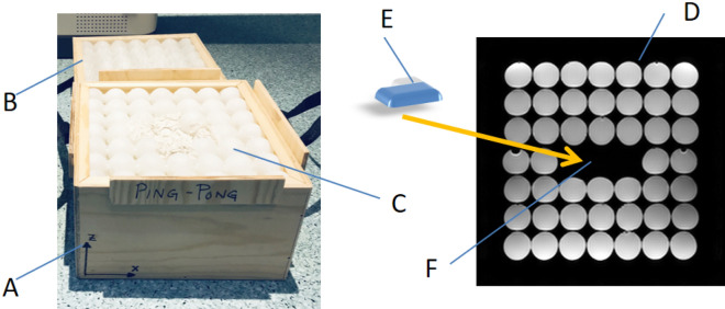
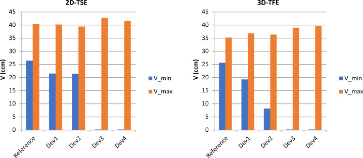
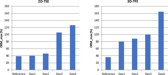
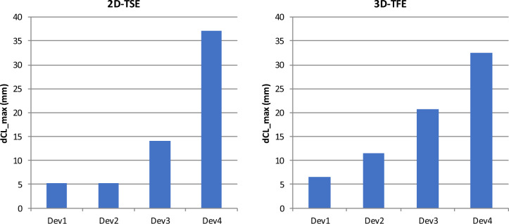
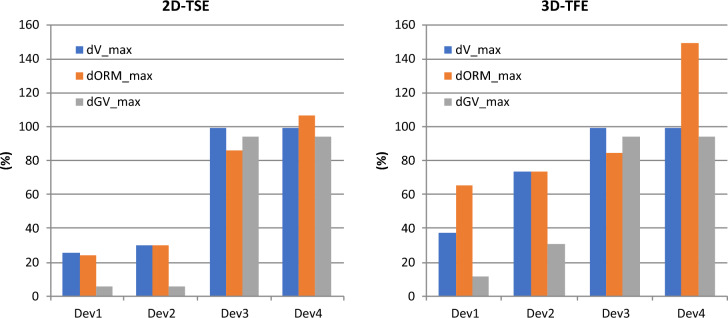
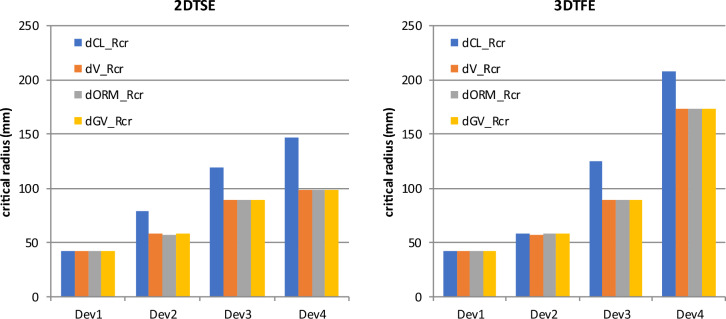
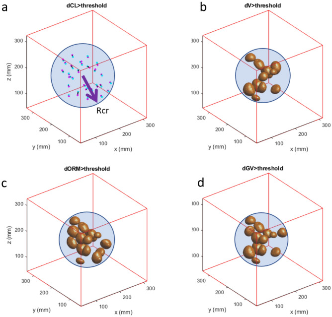
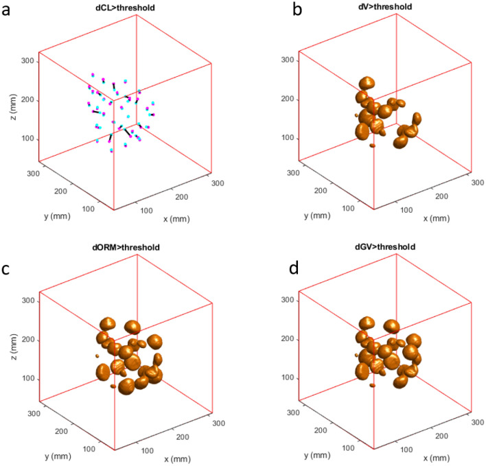
CMR at 3.0T in the presence of active cardiac implants remains a challenge due to susceptibility artifacts. Beyond a signal void that cancels image information, magnetic field inhomogeneities may cause distorted appearances of anatomical structures. Understanding influencing factors and the extent of distortion are a first step towards optimizing the image quality of CMR with active implants at 3.0T. All measurements were obtained at a clinical 3.0T scanner. An in-house designed phantom with a 3D cartesian grid of water filled spheres was used to analyze the distortion caused by four representative active cardiac devices (cardiac loop recorder, pacemaker, 2 ICDs). For imaging a gradient echo (3D-TFE) sequence and a turbo spin echo (2D-TSE) sequence were used. The work defines metrics to quantify the different features of distortion such as changes in size, location and signal intensity. It introduces a specialized segmentation technique based on a reaction-diffusion-equation. The distortion features are dependent on the amount of magnetic material in the active implants and showed a significant increase when measured with the 3D TFE compared to the 2D TSE. This work presents a quantitative approach for the evaluation of image distortion at 3.0T caused by active cardiac implants and serves as foundation for both further optimization of sequences and devices but also for planning of imaging procedures.

Keywords: Active implants; Artifacts; CMR; Distortion; Susceptibility.


Conflict of interest statement

Dr. Weiss is an employee of BIOTRONIK SE & Co. KG, Berlin, Germany, and Dr. Weber is an employee of Philips GmbH, Hamburg, Germany. Prof. Bauer is a scientific advisor for BIOTRONIK SE & Co. KG, Berlin, Germany. Also, this work has been partially funded by BIOTRONIK SE & Co. KG, Berlin, Germany. Dr. Reiter has no competing interests to declare.

Figures

Figure 1
Figure 1
Phantom. The cubic phantom consists of a bottom part A and a top part B allowing positioning of the implant E in the preformed space F in the middle slice (D, yellow arrow). The spheres C are filled with plain water and are glued together for better mechanical stability. For the measurements, the top part is mounted on the bottom part. The phantom is marked with a coordinate system allowing a defined orientation. All measurements were performed in the orientation: X: left- right, Y: foot-head, Z: bottom up.
Figure 2
Figure 2
Impact of the implant type and the scanning sequence on the volumes of the reconstructed spheres. V_min and V_max of the reference scan shows the systemic distortion at the borders of the field of view. For Dev1 and Dev2, none of the spheres completely disappears from the field of view. whereas in case of Dev3 and Dev 4, some spheres appear completely suppressed.
Figure 3
Figure 3
Impact of the implant type and the scanning sequence on out-of-round measure (ORM) of the reconstructed spheres. For the 2D-TSE, Dev1 and Dev2 show only very little ORM, whereas Dev3 and Dev4 show a significant increase. For the 3D-TFE, all devices show significantly more ORM than the reference scan.
Figure 4
Figure 4
Impact of the implant type and the scanning sequence on the maximum shift of the reconstructed sphere centers. For the 2D-TSE, Dev1 and Dev2 induce a maximum displacement of 5 mm, whereas Dev4 shows a displacement of 37 mm. For the 3D-TFE, the displacement caused by Dev2 more than doubles.
Figure 5
Figure 5
Impact of the implant type and the scanning sequence on the changes relative to the reference regarding the entities volume, out-of-round measure and gray values of the reconstructed spheres.
Figure 6
Figure 6
Impact of the implant type and the scanning sequence on the critical radius up to which a measurable effect can be demonstrated.
Figure 7
Figure 7
Exemplary result for Dev3 scanned with 2D-TSE showing the reconstructed spheres inside the critical radius Rcr. (a) sphere centers shifted by more than the threshold value from light blue dot (reference) to magenta dot as indicated by the black lines, (b) spheres affected by change in volume lager than a threshold value, (c) spheres affected by an ORM change lager than a threshold value, (d) spheres affected by gray value changes lager than a threshold value. The spheres outside of the critical radius are not shown.
Figure 8
Figure 8
Exemplary result for Dev3 scanned with 3D-TFE showing the reconstructed spheres inside the critical radius. (a) sphere centers shifted by more than the threshold value from light blue dot (reference) to magenta dot as indicated by the black lines, (b) spheres affected by change in volume lager than a threshold value, (c) spheres affected by an ORM change lager than a threshold value, (d) spheres affected by gray value changes lager than a threshold value. The spheres outside of the critical radius are not shown.

Similar articles

References

    1. Schulz-Menger J, Bluemke DA, Bremerich J, Flamm SD, Fogel MA, Friedrich MG, et al. Standardized image interpretation and post-processing in cardiovascular magnetic resonance - 2020 update: Society for cardiovascular magnetic resonance (SCMR): Board of trustees task force on standardized post-processing. J. Cardiovasc. Magn. Reson. 2020;22(1):19. doi: 10.1186/s12968-020-00610-6. - DOI - PMC - PubMed
    1. Raatikainen MJP, Arnar DO, Merkely B, Nielsen JC, Hindricks G, Heidbuchel H, et al. A decade of information on the use of cardiac implantable electronic devices and interventional electrophysiological procedures in the European Society of Cardiology Countries: 2017 Report from the European Heart Rhythm Association. Europace. 2017;19(suppl_2):ii1–ii90. doi: 10.1093/europace/eux258. - DOI - PubMed
    1. Duru F, Luechinger R, Scheidegger MB, Lüscher TF, Boesiger P, Candinas R. Pacing in magnetic resonance imaging environment: Clinical and technical considerations on compatibility. Eur. Heart J. 2001;22(2):113–124. doi: 10.1053/euhj.2000.2149. - DOI - PubMed
    1. Luechinger R, Zeijlemaker VA, Boesiger P, Duru F. Potential harmful effects of magnetic resonance imaging in pacemaker patients should not be underestimated. Europace. 2006;8(5):389–390. doi: 10.1093/europace/eul027. - DOI - PubMed
    1. Luechinger R, Zeijlemaker VA, Pedersen EM, Mortensen P, Falk E, Duru F, et al. In vivo heating of pacemaker leads during magnetic resonance imaging. Eur. Heart J. 2005;26(4):376–83. doi: 10.1093/eurheartj/ehi009. - DOI - PubMed