

Development and characterization of a dedicated dose monitor for ultrahigh-dose-rate scanned carbon-ion beams
- PMID: 38773165
- PMCID: PMC11109334
- DOI: 10.1038/s41598-024-62148-2
Development and characterization of a dedicated dose monitor for ultrahigh-dose-rate scanned carbon-ion beams
Abstract
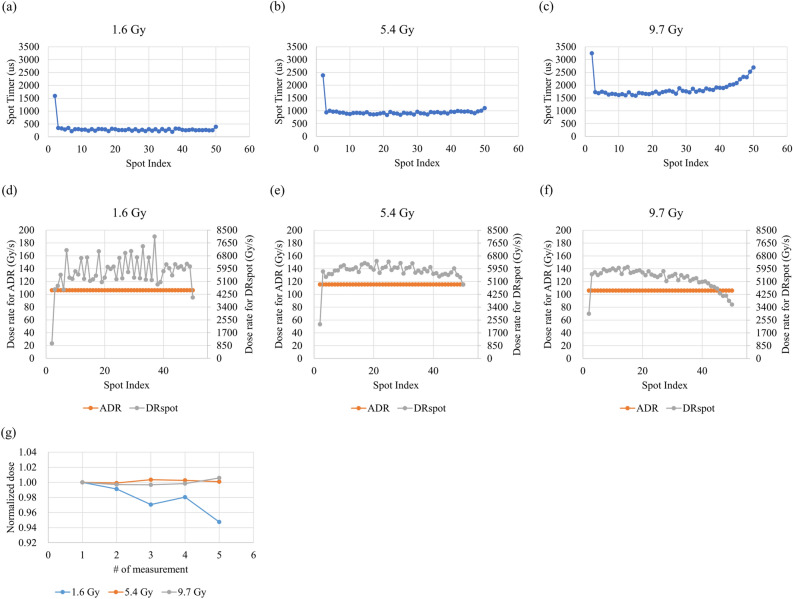
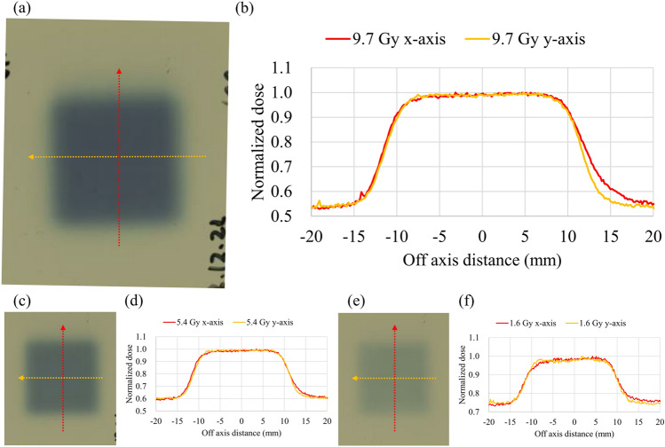
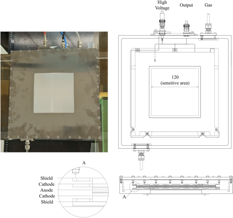
The current monochromatic beam mode (i.e., uHDR irradiation mode) of the scanned carbon-ion beam lacks a dedicated dose monitor, making the beam control challenging. We developed and characterized a dedicated dose monitor for uHDR-scanned carbon-ion beams. Furthermore, a simple measurable dose rate (dose rate per spot (DRspot)) was suggested by using the developed dose monitor and experimentally validating quantities relevant to the uHDR scanned carbon-ion beam. A large plane-parallel ionization chamber (IC) with a smaller electrode spacing was used to reduce uHDR recombination effects, and a dedicated operational amplifier was manufactured for the uHDR-scanned carbon-ion beam. The dose linearity of the IC was within ± 1% in the range of 1.8-12.3 Gy. The spatial inhomogeneity of the dose response of the IC was ± 0.38% inside the ± 40-mm detector area, and a systematic deviation of approximately 2% was measured at the edge of the detector. uHDR irradiation with beam scanning was tested and verified for different doses at the corresponding dose rates (in terms of both the average dose rate and DRspot). We confirmed that the dose monitor can highlight the characteristics (i.e., dose, dose rate, and dose profile) of uHDR-scanned carbon-ion beams at several dose levels in the monochromatic beam mode.
© 2024. The Author(s).
Conflict of interest statement
Takuto Miyoshi, Takuya Nomura, Takashi Toyoda, Masaki Shimizu, Yoshiaki Kuwana, Masumi Umezawa are employees of Hitachi, Ltd. The remaining authors have no conflicts to declare.
Figures


Similar articles
-
Investigation of Ionization Chamber Characteristics for Ultrahigh-dose-rate Scanned Carbon-ion Beams.In Vivo. 2024 Sep-Oct;38(5):2220-2227. doi: 10.21873/invivo.13686. In Vivo. 2024. PMID: 39187321 Free PMC article.
-
Characterization of a diode dosimeter for UHDR FLASH radiotherapy.Med Phys. 2023 Sep;50(9):5875-5883. doi: 10.1002/mp.16474. Epub 2023 May 30. Med Phys. 2023. PMID: 37249058 Free PMC article.
-
Development of a Real-Time Pixel Array-Type Detector for Ultrahigh Dose-Rate Beams.Sensors (Basel). 2023 May 9;23(10):4596. doi: 10.3390/s23104596. Sensors (Basel). 2023. PMID: 37430512 Free PMC article.
-
Feasibility of Synchrotron-Based Ultra-High Dose Rate (UHDR) Proton Irradiation with Pencil Beam Scanning for FLASH Research.Cancers (Basel). 2024 Jan 3;16(1):221. doi: 10.3390/cancers16010221. Cancers (Basel). 2024. PMID: 38201648 Free PMC article.
-
FLASH radiotherapy treatment planning and models for electron beams.Radiother Oncol. 2022 Oct;175:210-221. doi: 10.1016/j.radonc.2022.08.009. Epub 2022 Aug 11. Radiother Oncol. 2022. PMID: 35964763 Review.
Cited by
-
Ultra-high dose rate (FLASH) carbon ion irradiation inhibited immune suppressive protein expression on Pan02 cell line.J Radiat Res. 2025 Jan 22;66(1):97-102. doi: 10.1093/jrr/rrae091. J Radiat Res. 2025. PMID: 39724928 Free PMC article.
-
The evolution of FLASH radiotherapy: a bibliometric analysis.Front Oncol. 2025 May 15;15:1580848. doi: 10.3389/fonc.2025.1580848. eCollection 2025. Front Oncol. 2025. PMID: 40444076 Free PMC article.
-
Investigation of Ionization Chamber Characteristics for Ultrahigh-dose-rate Scanned Carbon-ion Beams.In Vivo. 2024 Sep-Oct;38(5):2220-2227. doi: 10.21873/invivo.13686. In Vivo. 2024. PMID: 39187321 Free PMC article.
-
Dosimetric impact of stopping power for human bone porosity with dual-energy computed tomography in scanned carbon-ion therapy treatment planning.Sci Rep. 2024 Jul 29;14(1):17440. doi: 10.1038/s41598-024-68312-y. Sci Rep. 2024. PMID: 39075135 Free PMC article.
References
Grants and funding
LinkOut - more resources
Full Text Sources
