. 2024 Apr 25;9(5):262.
doi: 10.3390/biomimetics9050262.

Reducing Inert Materials for Optimal Cell-Cell and Cell-Matrix Interactions within Microphysiological Systems

Affiliations

Reducing Inert Materials for Optimal Cell-Cell and Cell-Matrix Interactions within Microphysiological Systems

Claudia Olaizola-Rodrigo et al. Biomimetics (Basel). .

Abstract

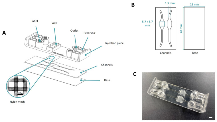
In the pursuit of achieving a more realistic in vitro simulation of human biological tissues, microfluidics has emerged as a promising technology. Organ-on-a-chip (OoC) devices, a product of this technology, contain miniature tissues within microfluidic chips, aiming to closely mimic the in vivo environment. However, a notable drawback is the presence of inert material between compartments, hindering complete contact between biological tissues. Current membranes, often made of PDMS or plastic materials, prevent full interaction between cell types and nutrients. Furthermore, their non-physiological mechanical properties and composition may induce unexpected cell responses. Therefore, it is essential to minimize the contact area between cells and the inert materials while simultaneously maximizing the direct contact between cells and matrices in different compartments. The main objective of this work is to minimize inert materials within the microfluidic chip while preserving proper cellular distribution. Two microfluidic devices were designed, each with a specific focus on maximizing direct cell-matrix or cell-cell interactions. The first chip, designed to increase direct cell-cell interactions, incorporates a nylon mesh with regular pores of 150 microns. The second chip minimizes interference from inert materials, thereby aiming to increase direct cell-matrix contact. It features an inert membrane with optimized macropores of 1 mm of diameter for collagen hydrogel deposition. Biological validation of both devices has been conducted through the implementation of cell migration and cell-to-cell interaction assays, as well as the development of epithelia, from isolated cells or spheroids. This endeavor contributes to the advancement of microfluidic technology, aimed at enhancing the precision and biological relevance of in vitro simulations in pursuit of more biomimetic models.

Keywords: inert material; macro/micropores; membranes; mesh; microfluidic devices; microphysiological systems (MPS); migration; organ-on-a-chip (OoC); spheroids.


Conflict of interest statement

I. Ochoa, R. Monge and S. Oliván are promoters and consultants for BEOnChip S.L.

Figures

Figure 1
Figure 1
Design of Mesh device. (A) The device is composed of several parts: COP injection part, nylon membrane with 150 × 150 µm pores, COC Flex channels layer and COP base layer. (B) This section provides a visual representation of the design and dimensions of each layer, showcasing how they fit together to form the final device. (C) Final device. Scale bar: 5 mm.
Figure 2
Figure 2
Design of Macropore device. (A) The device consists of several parts: COP injection part, COC Flex wells layer, COC Flex tri-pore membrane layer, COC Flex channels layer and COP base layer. (B) This section provides a visual representation of the design and dimensions of each layer, showcasing how they fit together to form the final device. (C) Final device. Scale bar: 5 mm.
Figure 3
Figure 3
Validation of the Macropore device. (A) Top-down perspective and z-stack imaging of the recently inoculated well containing collagen gel infused with green fluospheres, with the seeding volume 3 µL. (B) Top-down view and z-stack imaging of the well containing the polymerized gel with freshly introduced PBS infused with red fluospheres. Scale bar: 1000 µm. At the bottom of the figure is a technical description of the schematic diagrams illustrating the structure and components of the well.
Figure 4
Figure 4
Epithelium generation. (A) Top-down perspective of the evolution of the monolayer at different time points (0, 24, 144, and 288 h). Insets represent details of cell spreading and colonization over the membrane. Scale bar top images: 1000 µm. Scale bar bottom images: 100 µm. (B) Schematic representation of the application. (C) Confocal imaging of the monolayer (20×) after immunolabelling of the tight junctions with ZO-1 (red) and nuclei counter labelling with Hoechst (cyan). The inset (40×, oil immersion) depicts the tight junctions of the monolayer at the selected zone. Scale bar: 100 µm. (D) Graph illustrating the percentage of the HCT cell monolayer’s area of occupancy on the nylon membrane over time.
Figure 5
Figure 5
Migration assay on Mesh device. (A) Schematic representation of the application. (B) Time evolution of the invasive front of U-87 MG spheroids at different time points. The first row, corresponding to bright field images of the experiment, illustrates the invasion in the planar direction. The last two rows, corresponding to confocal images (10×) of the same experiment, depict the invasion front in the z-direction. Scale bar: 100 µm. (C) The progression of the invaded area as U-87 cells migrate throughout the studied 5 days.
Figure 6
Figure 6
Migration assay and endothelium generation on Mesh device. (A) Confocal imaging captures the invasion of U-87 MG cells towards the perfusion channel over 96 h, alongside their interactions with endothelial HBEC cells during the 24 h period at 120 and 144 h. Scale bar: 100 µm. (B) Schematic representation of the application. (C) Z-stack reconstruction illustrating interactions between U-87 MG cells (in red) and endothelial cells (stained in green with their nuclei counterstained in cyan). Scale bar: 100 µm.
Figure 7
Figure 7
Migration assay on Macropore device. (A) Illustration depicting the experimental setup. (B) Analysis of the evolution of U-87 cell migration within the Macropore device over successive days, quantifying the invaded area as a percentage. (C) Images captured under phase contrast and fluorescence microscopy illustrating the development of a spheroid initially composed of 1000 U87 cells (top view), with the outline of the macropore visible just below. At 96 h, cell migration is already observable. (D) Confocal microscopy images (3D projection, lateral view) with cells artificially colored in yellow, highlighting their movement towards the channel. Scale bar: 100 μm.
Figure 8
Figure 8
Co-culture assay with epithelial cells and fibroblasts on Macropore device. (A) Phase contrast images showing the Caco-2 cells (maximum height from the membrane) and HDF cells (intermedium height from the membrane). Yellow arrows have been added to mark their location. (B) Schematic representation of the application. (C) Confocal image (3D projection, lateral view). HDF are shown in red and Caco2 are shown in green. Scale bar: 100 μm.
Figure 9
Figure 9
Permeability assessment. (A) Evolution of the quantity of fluorescein diffused through a 4 mg mL−1 collagen hydrogel in the chips with the studied membranes (PC, Mesh, and Macropore). (B) Permeability coefficient values at 90 and 180 min intervals for the three chips presented: the control chip featuring the PC membrane, the Mesh (chip containing the nylon membrane), and the Macropore. Data are represented as the mean  ±  SEM (** p  <  0.01; n  =  3).

Similar articles

References

    1. Zhang J.X.J., Hoshino K. Microfluidics and Micro Total Analytical Systems. Mol. Sensors Nanodevices. 2014:103–168. doi: 10.1016/b978-1-4557-7631-3.00003-x. - DOI
    1. Convery N., Gadegaard N. 30 Years of Microfluidics. Micro Nano Eng. 2019;2:76–91. doi: 10.1016/j.mne.2019.01.003. - DOI
    1. Wang K., Man K., Liu J., Liu Y., Chen Q., Zhou Y., Yang Y. Microphysiological Systems: Design, Fabrication, and Applications. ACS Biomater. Sci. Eng. 2020;6:3231–3257. doi: 10.1021/acsbiomaterials.9b01667. - DOI - PMC - PubMed
    1. Zhang S., Xu G., Wu J., Liu X., Fan Y., Chen J., Wallace G., Gu Q. Microphysiological Constructs and Systems: Biofabrication Tactics, Biomimetic Evaluation Approaches, and Biomedical Applications. Small Methods. 2023;8:2300685. doi: 10.1002/smtd.202300685. - DOI - PubMed
    1. Ingber D.E. Human organs-on-chips for disease modelling, drug development and personalized medicine. Nat. Rev. Genet. 2022;23:467–491. doi: 10.1038/s41576-022-00466-9. - DOI - PMC - PubMed

LinkOut - more resources