Review
. 2024 Feb 1;4(3):191-201.
doi: 10.1021/acsphyschemau.3c00064. eCollection 2024 May 22.

My Vision of Electric-Field-Aided Chemistry in 2050

Affiliations
Review

My Vision of Electric-Field-Aided Chemistry in 2050

Sason Shaik. ACS Phys Chem Au. .

Abstract

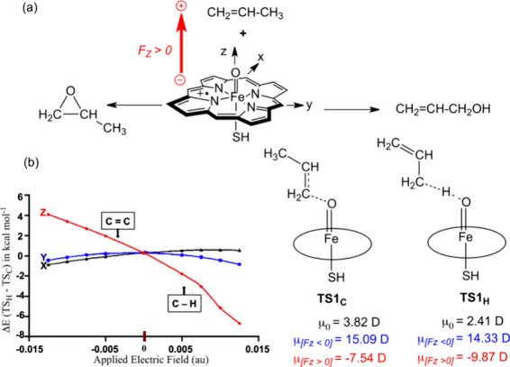
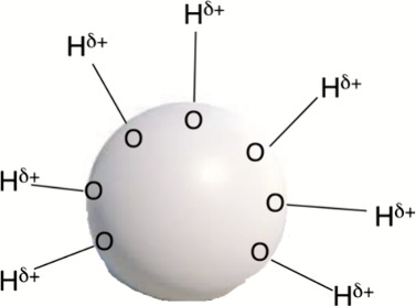
This manuscript outlines my outlook on the development of electric-field (EF)-mediated-chemistry and the vision of its state by 2050. I discuss applications of oriented-external electric-fields (OEEFs) on chemical reactions and proceed with relevant experimental verifications. Subsequently, the Perspective outlines other ways of generating EFs, e.g., by use of pH-switchable charges, ionic additives, water droplets, and so on. A special section summarizes conceptual principles for understanding and predicting OEEF effects, e.g., the "reaction-axis rule", the capability of OEEFs to act as tweezers that orient reactants and accelerate their reaction, etc. Finally, I discuss applications of OEEFs in continuous-flow setups, which may, in principle, scale-up to molar concentrations. The Perspective ends with the vision that by 2050, OEEF usage will change chemical education, if not also the art of making new molecules.


Conflict of interest statement

The author declares no competing financial interest.

Figures

Figure 1
Figure 1
Bond heterolysis in a solvent is due to crossing of the covalent and ionic curves along the bond stretching coordinate. An ion pair, Mz+:Az–, which creates an oriented electric field, leads to rate enhancement. The Figure is reproduced with permission from ref (20), Figure 9. Copyright (1999) Wiley VCH.
Figure 2
Figure 2
(a) C–H hydroxylation vs C=C epoxidation of propene in the presence of OEEFs (in au; 1 au = 51.4 V/Å) along the three Cartesian axes. FZ points along the Fe=O bond of Compound I. The conventions for positive and negative FZ vectors follow, here and elsewhere in the text, the Gaussian software. (b) The direction of FZ determines the regiochemical preference: FZ< 0 prefers C=C epoxidation, while FZ> 0 prefers C–H hydroxylation. Shown on the right-hand side are the dipole moments (in Debye units, D) for the initial states (μ0) and in the respective TSs, for the two directions of FZ. Note that FX and FY have hardly any effect on either reactivity or product selectivity. The Figure is adapted with permission from ref (4), Figure 3. Copyright (2016) Nature Publishing Group.
Figure 3
Figure 3
(a) The endo- and exo-TS structures for the Diels–Alder reaction of cyclopentadiene and maleic anhydride. Underneath the structures are plots of barrier heights as a function of FZ (FX, FY have virtually no impact on the barrier height). (b) The TS structures on the right-hand side show that as FZ becomes more negative, the asynchronicity of the two forming C–C bond lengths in the TS increases and leads eventually to zwitterionic intermediates. The Figure is adapted with permission from Figure 6 in ref (4). Copyright (2016) Nature Publishing Group.
Figure 4
Figure 4
An experimental setup for testing the prediction of the OEEF effect on a Diels–Alder reaction. The setup employs an STM tip and a gold surface that orient the reactants along the OEEF vector created by the voltage gauge. The product formation event was verified by monitoring the current flow as the adduct was formed and by breaking the junction between the STM tip and the adduct, that stop the current. The Figure is adapted with permission from ref (3). Copyright (2018) of Royal Society of Chemistry.
Figure 5
Figure 5
OEEF, due to the ion separation in the double-layer of an electrochemical cell (without a Faradaic current), controls the product-selectivity of the rhodium-porphyrin-induced rearrangement of the azo compound. The Rh complex is linked to an electrode coated by an insulator that prevents a Faradaic current flow. The voltage and its sign are seen to affect the product-selectivity ratio 5/6. The Figure is adapted with permission from ref (4), Figure 19. Copyright (2016) Nature Publishing Group.
Figure 6
Figure 6
(a) OEEF generation due to surface charging by an applied voltage. The surface charging polarizes the π-anion catalyst, which develops a dipole (μZ) and, hence, a corresponding OEEF. Note that here, the direction of the dipole moment follows chemical convention wherein the arrowhead is the negative pole. (b) The OEEF prefers the production of 6(D), while in the absence of OEEF, the major product is 5(A). The Figure is adapted from ref (7). Copyright (2017) American Chemical Society.
Figure 7
Figure 7
(a) TEMPO derivatives and corresponding changes in the BDE values (kcal/mol) of O–CH3 due to the pH switch that deprotonates the carboxylic acid substituent (−CO2H). (b) Stabilization of the nitroxyl radical by the enhancement of resonance structure II, due to the OIEF effect of the negative charge. The Figure is reproduced with permission from ref (3), Scheme 6. Copyright (2018) Royal Society of Chemistry.
Scheme 1
Scheme 1. A Schematic Sketch of a Molecular Setup, Which Is Used in Ref (14), to Enhance the Rate of the Diels-Alder (DA) Reaction
The setup includes a built-in ammonium group, which is generated by a pH switch, and which thereby exerts an OIEF that lowers the energy of the DA-TS. The scheme was designed and drawn by the author of this Perspective.
Scheme 2
Scheme 2. A Cartoon Representation of a Water Droplet and Some of Its On-Surface External O–H Bonds
These bonds exert electric fields which affect chemical reactivity. The scheme was designed by the author of the Perspective.
Scheme 3
Scheme 3. Computed Interaction Energy of the OEEF (FZ = 0.64 V/Å) with the Halogen Bond H3N–Cl2 is 25.3 kcal/mol
Data from the respective supporting document (Table S35) of ref (53). Adapted from ref (53). Copyright (2019) American Chemical Society.
Scheme 4
Scheme 4. Curly Arrow Pushing, the Reaction Axis (RA), and the OEEF Direction (FZ) for: (a) a Diels-Alder (DA) Reaction and (b) an SN2 Reaction
The doubly headed arrow in (a) indicates that the OEEF can in principle affect reactivity in both directions of the Z axis. The scheme was produced by the author of the present Perspective.
Figure 8
Figure 8
Impact of OEEFs on the Menshutkin SN2 reaction, along the X, Y, and Z directions. It is seen that FZ·> 0 leads to barrier lowering, while flipping the FZ direction raises the barrier. OEEFs along the X and Y directions exhibit little or no effects. The Figure is adapted from ref (29). Copyright (2018) American Chemical Society.
Figure 9
Figure 9
(a, b) Electric-field-induced catalysis in electromicrofluidic reactors, which involve MWCNTs. Applied voltages in opposite directions charge the surfaces that polarize the MWCNTs and induce oppositely oriented macrodipoles ((a) vs (b)) that generate corresponding OEEFs. The substrate (S) is deposited on the MWCNT surface using planar molecules like pyrene which is attached to substrate S. The OEEFs, due to the polarized MWCNT, enhance the rate of product (P) formation from S. Provided with courtesy of the lead author of ref (8), S. Matile. The Figure is reproduced with permission under a Creative Commons Attribution license from ref (8). Copyright (2023) American Association for the Advancement of Science.
Figure 10
Figure 10
An example for S and P for the transformation of 3-hydroxo epoxide (S) to an ether molecule (P). The pyrene rings in S and P serve as “adhesives” which attach the reacting molecule (S) on the surface of the MWCNT (in Figure 9, the pyrenes are depicted as small rectangles). Provided with courtesy of S. Matile, the author of ref (8). The Figure is reproduced with permission under a Creative Commons Attribution license from ref (8). Copyright (2023) American Association for the Advancement of Science.

References

    1. Effects of Electric Fields on Structure and Reactivity: New Horizons in Chemistry ;Shaik S., Stuyver T., Eds.; Royal Society of Chemistry, 2021; pp 1–428.10.1039/9781839163043. - DOI
    1. Shaik S.; Danovich D.; Dubey K. D.; Stuyver T.. The Impact of Electric Fields on Chemical Structure and Reactivity. In Effects of Electric Fields on Structure and Reactivity: New Horizons in Chemistry ;Royal Society of Chemistry, 2021; pp12–70. 10.1039/9781839163043-00012. - DOI
    1. Shaik S.; Ramanan R.; Danovich D.; Mandal D. Structure and Reactivity/Selectivity Control by Oriented-External Electric Fields. Chem. Soc. Rev. (Tutorial) 2018, 47 (14), 5125–5145. 10.1039/C8CS00354H. - DOI - PubMed
    1. Shaik S.; Mandal D.; Ramanan R. Oriented Electric Fields as Future Smart Reagents in Chemistry. Nat. Chem. 2016, 8, 1091–1098. 10.1038/nchem.2651. - DOI - PubMed
    1. Ciampi S.; Darwish N.; Aitken H. M.; Diez-Perez I.; Coote M. L. Harnessing electrostatic catalysis in single molecule, electrochemical and chemical systems: a rapidly growing experimental tool box. Chem. Soc. Rev. (Tutorial) 2018, 47 (14), 5146–5164. 10.1039/C8CS00352A. - DOI - PubMed

LinkOut - more resources