. 2024 May 27;14(1):12078.
doi: 10.1038/s41598-024-62997-x.

Stabilization and correction of aberrated laser beams via plasma channelling

Affiliations

Stabilization and correction of aberrated laser beams via plasma channelling

Alexandre Rondepierre et al. Sci Rep. .

Abstract

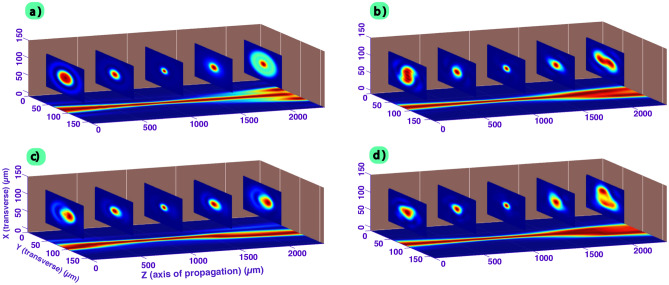
High-power laser applications, and especially laser wakefield acceleration, continue to draw attention through various research topics, and may bring many industrial applications based on compact accelerators, from ultrafast imaging to cancer therapy. However, one main step towards this is the arch issue of stability. Indeed, the interaction of a complex, aberrated laser beam with plasma involves a lot of physical phenomena and non-linear effects, such as self-focusing and filamentation. Different outcomes can be induced by small laser instabilities (i.e. laser wavefront), therefore harming any practical solution. One promising path to be explored is the use of a plasma channel to possibly guide and correct aberrated beams. Complex and costly experimental facilities are required to investigate such topics. However, one way to quickly and efficiently explore new solutions is numerical simulations, especially Particle-In-Cell (PIC) simulations if, and only if, one is confidently implementing such aberrated beams which, contrary to a Gaussian beam, do not have analytical solutions. In this research, we propose two new advancements: the correct implementation of aberrated laser beams inside a 3D PIC code, showing a great consistency, under vacuum, compared to the calculations with Fresnel theory); and the correction of their quality via the propagation inside a plasma channel. We demonstrate improvements in the beam pattern, becoming closer to a single plasma mode with less distortions, and thus suggesting a better stability for the targeted application. Through this confident calculation technique for distorted laser beams, we are now expecting to proceed with more accurate PIC simulations, closer to experimental conditions, and obtained results with plasma channels indicate promising future research.


Conflict of interest statement

The authors declare no competing interests.

Figures

Figure 1
Figure 1
Procedure to set the initial field in a PIC code. Here, an experimental beam, chosen as the initial beam, has been propagated through Fresnel integral up to the distance that corresponds to the cell number Zi, where the transverse field amplitude and phase is inserted. This method works with any kind of beam (either experimental and numerical-defined).
Figure 2
Figure 2
Global calculations conducted with the Fresnel propagator tool. The initial beam (amplitude and wavefront, left side) is propagated in a meters scale range before reaching the focal region, where multiple slices at Zi are extracted for their insertion inside the PIC code (right side).
Figure 3
Figure 3
Example of a 2 mm length plasma channel used in the PIC simulation with sextic (R6) function for the gradient. (a) Transverse relative electronic density ((X,Y) plane); (b) 1D profile along either X or Y direction, taken at the center of the channel; (c) Evolution of the electronic density as function of the propagation distance Z in the case of a maximum density of 5 × 1018 cm-3.
Figure 4
Figure 4
Comparison of the results obtained from Fresnel calculation and with conventional PIC simulation in the case of a Gaussian beam without aberrations (top side) and in the case of an aberrated beam (bottom side, TTA configuration (astigmatism and trefoil, as described in)). From left to right, the laser is propagated and the normalized transverse intensity ((X,Y) plane) is plotted up to 2.5 mm of propagation. A high consistency between the two methods is obtained.
Figure 5
Figure 5
Normalized transverse intensity profiles of the laser ((X,Y) plane) for 5 different positions along the direction of propagation (0, 0.5, 1, 1.5 and 2 mm). The normalized 2D intensity profile ((Y,Z), taken at X/2) as function of the propagation distance is projected below. In each cases (a) Spherical aberration, (b) astigmatism 0, (c) horizontal Coma, (d) TTA a total RMS value of λ/10 for the wavefront error is used.
Figure 6
Figure 6
Comparison of the aberrated laser propagation (TTA configuration, total RMS wavefront error of λ/5) in vacuum or in plasma in the case of a sextic channel profile (R6) and with a density of 5 × 1018 cm-3. (a) and (b) corresponds to the normalized transverse intensity profiles of the laser ((X,Y) plane) for 5 different positions along the direction of propagation (0, 0.5, 1, 1.5 and 2 mm). The normalized 1D intensity profile ((Y,Z), taken at X/2) as function of the propagation distance is projected below (the normalization has been conducted using the maximum value reached in the case of the propagation inside the plasma and the plasma position is shown in black dashed lines.). The transverse intensity profile obtained at the waist position are shown in (c) for plasma and in (d) for vacuum. The 1D intensity profile after 1 mm of propagation (e) and 2 mm (f) inside the plasma are also plotted (respectively (g) and (h) in vacuum).
Figure 7
Figure 7
Laser radius size (at (1/e)2 intensity, in μm) as function of the distance of propagation (μm). (a) The TTA and Spherical Aberration (SA) configurations are compared with the Gaussian case (aberration free) in vacuum and in plasma. (b) The effect of various plasma densities (From 1018 to 1019 cm-3), plasma shapes (one case with R2, else R6) or amplitude of aberration (total RMS value of λ/10 or λ/5) on the TTA configuration is shown. The plasma position is plotted in black dashed lines.

References

    1. Tajima T, Dawson JM. Laser electron accelerator. Phys. Rev. Lett. 1979;43:267. doi: 10.1103/PhysRevLett.43.267. - DOI
    1. Madey JM. Stimulated emission of bremsstrahlung in a periodic magnetic field. J. Appl. Phys. 1971;42:1906–1913. doi: 10.1063/1.1660466. - DOI
    1. Labat M, et al. Seeded free-electron laser driven by a compact laser plasma accelerator. Nat. Photonics. 2023;17:150–156. doi: 10.1038/s41566-022-01104-w. - DOI
    1. Oz E, et al. Ionization-induced electron trapping in ultrarelativistic plasma wakes. Phys. Rev. Lett. 2007;98:084801. doi: 10.1103/PhysRevLett.98.084801. - DOI - PubMed
    1. Suk H, Barov N, Rosenzweig JB, Esarey E. Plasma electron trapping and acceleration in a plasma wake field using a density transition. Phys. Rev. Lett. 2001;86:1011. doi: 10.1103/PhysRevLett.86.1011. - DOI - PubMed