. 2024 May 30;14(1):12448.
doi: 10.1038/s41598-024-63154-0.

Capillary wave tweezer

Affiliations

Capillary wave tweezer

Bethany Orme et al. Sci Rep. .

Abstract

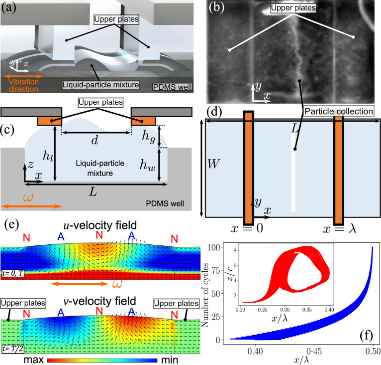
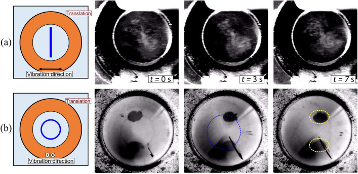
Precise control of microparticle movement is crucial in high throughput processing for various applications in scalable manufacturing, such as particle monolayer assembly and 3D bio-printing. Current techniques using acoustic, electrical and optical methods offer precise manipulation advantages, but their scalability is restricted due to issues such as, high input powers and complex fabrication and operation processes. In this work, we introduce the concept of capillary wave tweezers, where mm-scale capillary wave fields are dynamically manipulated to control the position of microparticles in a liquid volume. Capillary waves are generated in an open liquid volume using low frequency vibrations (in the range of 10-100 Hz) to trap particles underneath the nodes of the capillary waves. By shifting the displacement nodes of the waves, the trapped particles are precisely displaced. Using analytical and numerical models, we identify conditions under which a stable control over particle motion is achieved. By showcasing the ability to dynamically control the movement of microparticles, our concept offers a simple and high throughput method to manipulate particles in open systems.

Keywords: Acoustic; Capillary; Microparticles; Streaming; Vibration.


Conflict of interest statement

The authors declare no competing interests.

Figures

Figure 1
Figure 1
(a) Depiction of the experimental setup. A capillary wave is generated between the upper parallel plates by vibrating the PDMS well in the horizontal (x) direction. (b) Top view of the experiment which shows the orientation of the upper plates and the particle collection in the PDMS well. (c) Side view depiction of the experimental setup, where the upper plates with a separation distance (d) are placed on top of the liquid-particle mixture contained within the PDMS well of fixed depth (hw) with a gap (hg) between the well plate and parallel plates; the total height of the liquid volume is hl=hg+hw. (d) Top view depiction of the experimental setup indicating the length (L=8 mm) and width (W=3 mm) of the PDMS well. (e) The velocity fields in the x- and y-directions (u and v velocity fields, respectively) obtained via simulations. The base is vibrated such that a wave of 1 wavelength is setup. The color map indicates the strength of the fields, the arrows indicate the direction of the fields. ‘N’ and ‘A’ represent the displacement nodes and antinodes, respectively, of the standing capillary wave. (f) Particle trajectory simulation in the flow fields, showing an asymptotic convergence to x=λ/2 over multiple cycles. Inset shows an example of the z and x position of a particle trapped in a streaming field; r is the particle radius.
Figure 2
Figure 2
Collection of melamine resin particles (r=5 μm) under the action of capillary wave at different amplitudes and plate separations (d), corresponding to different actuation frequencies and a liquid height hl=0.75 mm. The orange lines indicate the edge of the upper plates or the two nodes of the capillary wave. In the image with d=6 mm and V0=5 V, the blue dashed line represents the particles collected stably underneath the central capillary wave node and the red dashed line represents the the particles drawn underneath the upper plates.
Figure 3
Figure 3
Control of particle position using capillary tweezers. (a) Schematic drawing of the capillary wave and particle displacement. The current position of the upper plates is indicated by the solid orange lines while the dashed orange lines indicate their original positions. The blue solid line indicates the current position of the particles, while the dashed blue line indicates their original position. (b) Experimental sequence of particle displacement at a translation speed of vt= 0.1 mms-1 at an actuation amplitude of V0= 3 V. (c) vt= 0.5 mms-1 and actuation amplitude of V0= 6 V. (d) vt= 0.5 mms-1 and actuation amplitude of V0= 4 V. (e) vt= 0.5 mms-1 and actuation amplitude of V0=3 V. In all the experiments, the upper plate separation distance d= 3.5 mm, which corresponds to a frequency of f= 58 Hz for a capillary wave of one wavelength. The liquid height hl= 0.5 mm.
Figure 4
Figure 4
(a) Mapping showing the different collection states of particles at different actuation amplitudes (V0) and translation speeds (vt): stable collection between λ/4 and λ/2 (blue squares), unstable collection at λ/4 (black crosses) and dispersion (red circles). The dashed black line indicates the maximum tweezing speed estimates. (b) Collection times for glass particles (rp=5 μm) at different actuation amplitudes and liquid heights hl=0.5, 0.75 and 1 mm.
Figure 5
Figure 5
(a) Position of particles relative to the central wave node position (dp) at different actuation amplitudes and translation speeds. The red, grey and blue regions represent the position x=0 (underneath the upper plates), 0<x<λ/4 and λ/4<x<λ/2 (stable collection). (b) Depiction of dp under a capillary wave translating at a speed vt. The figure also depicts the forces acting on the particles during tweezing; Fd is the Stokes drag force due to capillary wave movement and Feq is the equivalent collection force time-averaged over a cycle due to the periodic inertial drag from the capillary wave.
Figure 6
Figure 6
Distance of particle collection line from the center of the capillary wave during translation, normalised with the capillary wavelength (dp/λ) at different capillary wave translation speeds (vt) and excitation voltages (V0). The closed markers represent the experiments for continuous translation and the open markers represent the experiments for stepped translation; hl=0.5 mm, d=3.5 mm (f=58 Hz). (b) Distance of particle collection line from the center of the capillary wave (dp) during stepped translation of the capillary wave in steps of 0.2 mm at speeds of 0.5 mms-1. A wait time is introduced to allow the particles to move towards the collection region at this high translation speeds.
Figure 7
Figure 7
(a) Collection of rp=10 μm glass particles through a capillary wave excited in a ring (diameter 6 mm); the base here is vibrated horizontally at V0=1 V and a frequency of 24 Hz, which sets up a wave of one wavelength, as indicated in the inset. (b) Collection of rp=10 μm glass particles through a capillary wave excited in a ring (diameter 8 mm); the base here is vibrated vertically at V0= 3V and frequency of 35 Hz, which sets up a wave of 1.5 wavelength, as indicated in the inset. The yellow dashed lines indicate particles trapped at the water-air interface. The images in (a,b) have been altered digitally by inversion and contrast adjustment for clarity.

References

    1. Ashkin, A. Acceleration and trapping of particles by radiation pressure. Phys. Rev. Lett.24, 156–159. 10.1103/PhysRevLett.24.156 (1970).
    1. Ashkin, A., Dziedzic, J. M., Bjorkholm, J. E. & Chu, S. Observation of a single-beam gradient force optical trap for dielectric particles. Opt. Lett.11, 288–290. 10.1364/OL.11.000288 (1986). - PubMed
    1. Cheng, K., Guo, J., Fu, Y. & Guo, J. Active microparticle manipulation: Recent advances. Sens. Actuat. A322, 112616. 10.1016/j.sna.2021.112616 (2021).
    1. Shundo, A., Hori, K., Penaloza, J., David, P. & Tanaka, K. Optical tweezers with fluorescence detection for temperature-dependent microrheological measurements. Rev. Sci. Instrum.84, 014103. 10.1063/1.4789429 (2013). - PubMed
    1. Zhang, H. & Liu, K.-K. Optical tweezers for single cells. J. R. Soc. Interface5, 671–690. 10.1098/rsif.2008.0052 (2008). - PMC - PubMed

LinkOut - more resources